No. 308, Gongxin Road, Industrial Park, Dongxing Town, Jingjiang City, Jiangsu Province, China
 [email protected]/ [email protected]
 English
 Español
 русский
 中文简体
中文简体 No. 308, Gongxin Road, Industrial Park, Dongxing Town, Jingjiang City, Jiangsu Province, China[email protected]/ [email protected]
Gas radiant tube heaters are combustion-based infrared heating systems that burn natural gas or propane inside a sealed metal tube and deliver radiant energy directly to people, floors, and equipment without heating the air as an intermediate step. This direct transfer of energy is why they routinely outperform forced-air systems by 20% to 50% in high-bay industrial buildings, and why they remain the default choice for warehouses, workshops, and vehicle service centers in cold climates.
Content
A gas radiant tube heater consists of a burner housing at one end, a long cylindrical steel tube typically 3 to 12 meters in length, a reflector panel positioned above the tube, and an induced-draft fan and flue at the opposite end. When the burner fires, the flame and hot combustion gases travel the full length of the tube, heating the metal wall to surface temperatures of 350°C to 600°C. That hot metal surface then emits infrared radiation, which the reflector directs downward into the occupied zone. The term low-intensity is often used for these systems because the tube surface temperature is comparatively low when measured against ceramic high-intensity heaters, yet still hot enough to produce meaningful radiant output. If you are new to the technology, this detailed guide to radiant tubes explains the common configurations and operating terminology.
Combustion starts in the burner housing, where an electronically controlled gas valve admits fuel into a mixing chamber. A venturi or premix blower draws combustion air and mixes it with the gas at a ratio tuned to a slight excess of air to ensure complete combustion and minimize carbon monoxide formation. A spark electrode or hot-surface igniter lights the mixture, and a flame rod or UV sensor confirms that ignition has occurred before the gas valve is allowed to stay open. This safety sequence repeats on every cold start and is controlled by a dedicated combustion controller. Because the entire combustion process is sealed inside the burner-tube system, no open flame ever contacts the occupied space and all combustion products are routed to the flue.
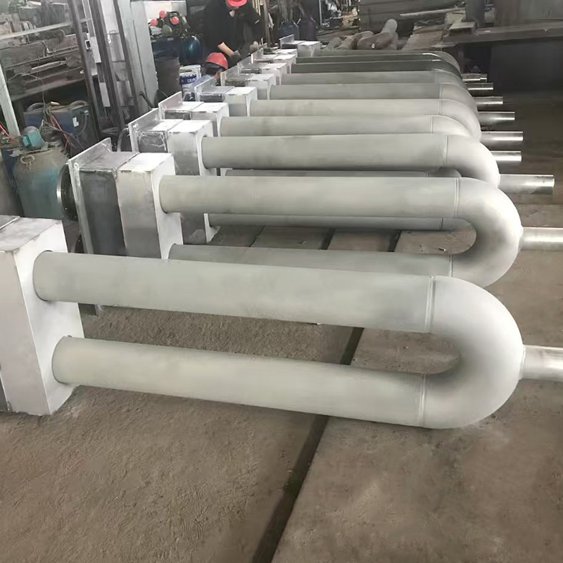
Once ignited, the flame creates a high-velocity jet of hot combustion gases that travels down the radiant tube. The tube wall absorbs heat from the gas stream through a combination of forced convection and radiation from the flame itself. The inner surface of the first 1 to 2 meters from the burner experiences the highest heat flux and is therefore manufactured from thicker or higher-alloy material. Internal baffles slow the gas near the burner and create turbulence along the tube so the heat transfer coefficient remains high. The design goal is to keep the tube surface as close to uniform as possible, with the flue-end temperature no more than 50°C cooler than the peak temperature. When the application requires the burner and flue at the same end, a U-shaped radiant tube is the standard geometry because it doubles the radiating length in the same ceiling footprint and simplifies gas piping and exhaust routing.
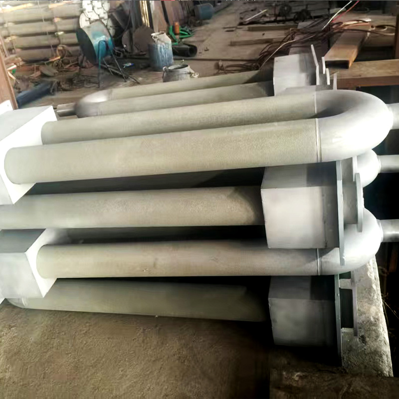 Wholesale U-Shaped Radiant Tube Manufacturer, Exporter CompanyJiangsu Huaye Technology Co., Ltd is China U-shaped radiant tube manufacturer and U-shaped radiant tube exporter company, We custom and w...View Product →
Understanding where the input fuel energy ends up is the fastest way to appreciate why radiant tube heaters are efficient. In a typical balanced system, roughly 62% of the gas energy leaves the tube surface as infrared radiation, and this is the portion doing the useful work. Another 12% is released as low-level convection from the hot tube and reflector, which warms the air adjacent to the ceiling but is still useful because it reduces the temperature differential across the building envelope. Flue losses average about 18% in an induced-draft system with a correctly set combustion ratio, although older or unmaintained burners can push that figure above 25%. The final 8% escapes through supporting brackets, reflector surfaces, and the vent pipe. Adding the radiant and convective shares together shows that well over 70% of the fuel input is delivered into the building, which is why a radiant tube heater can maintain comfortable conditions with a lower gas bill than a forced-air system of the same nominal capacity.
Infrared radiation from a tube surface behaves like visible light: it travels in straight lines, reflects off polished surfaces, and is absorbed by solid materials. Air is almost transparent to the wavelengths emitted by a tube in the 300°C to 600°C range, so the radiation passes through the air without warming it. When a floor slab or a piece of equipment absorbs that radiation, it begins to warm, and the warmed surface then releases its heat to the surrounding air through natural convection. This is why the floor in a radiant-heated building feels warm even on the coldest days, and why occupants feel comfortable at a lower thermostat setting than a convective system would require.
A reflector above each tube roughly doubles the usable radiant flux delivered to the floor below. The reflector is formed from a material with high reflectivity, usually polished aluminum, and its curvature is designed to project the downward radiation into a specific beam pattern. Wide-angle reflectors spread the energy evenly from mounting heights of 3 to 5 meters, while narrow reflectors produce a longer, narrower beam for heights of 8 meters or more. Reflector efficiency degrades gradually as the surface oxidizes or collects dust, which is why an annual cleaning and replacement interval of 8 to 12 years is common practice.
Gas radiant tube heaters are classified by the position of the combustion fan relative to the tube. In a pull-through or induced-draft configuration, the fan is mounted at the flue end and draws the combustion gases through the tube, placing the tube interior at a negative pressure. This is the predominant configuration for indoor industrial heaters, because small leaks in the tube or joints will pull air in rather than exhaust combustion products into the building. In a push-through or forced-draft configuration, the fan sits at the burner end and pushes the gas-air mixture through the tube, so the tube is at positive pressure and any leak can release combustion products. The push-through layout is therefore less common for indoor installations and generally limited to outdoor-rated equipment or double-wall tube designs. Fan speed in a pull-through system also determines the gas residence time, which directly shapes the tube temperature profile.
The tube surface temperature profile is the most informative diagnostic chart for a gas radiant tube heater. The curve shows temperature on the vertical axis and distance from the burner inlet on the horizontal axis. In a balanced system the temperature rises quickly during the first 0.5 meters, reaches a plateau between 1 and 3 meters, and then declines gradually as the flue is approached. A sharp temperature drop mid-tube usually means the internal baffle has shifted or the burner is incorrectly set. A heater that peaks at the very beginning and then falls steadily is likely over-fired, pushing hot gases through so fast that the back half of the tube contributes little radiant energy. The acceptable difference between peak temperature and flue-end temperature is roughly 50°C; when that difference exceeds 75°C, the burner-end section overheats and tube life shortens. Monitoring this profile once per season with a contact pyrometer through service ports is one of the best maintenance habits a facility can adopt.
The durability of a radiant tube heater depends mostly on the alloys used for the tube itself. Standard systems use aluminized steel for the full length with a heavier 309 or 310 stainless section at the burner end. Higher-grade materials are justified when the heater operates more than 3,000 hours per season or when the fuel contains sulfur compounds. Tube wall thickness is typically 2 to 3 mm, and expected service life ranges from 8 to 15 years depending on firing rate and maintenance quality.
| Component | Function | Typical Material | Maintenance Interval |
|---|---|---|---|
| Burner housing | Mixes gas and combustion air, ignites the mixture | Cast iron or coated steel | Annual inspection and leak test |
| Radiant tube | Transfers heat from combustion gases to the tube surface | Aluminized steel, 304/309/310 stainless | Inspect annually; replace every 8 to 15 years |
| Reflector | Directs upward infrared radiation downward | Polished aluminum or stainless steel | Clean annually |
| Induced-draft fan | Draws flue gases through the tube | Galvanized steel with sealed motor | Grease bearings annually |
| Gas valve train | Regulates fuel flow and shuts off on safety lockout | Brass and stainless steel | Annual functional test |
| Controls | Ignition, flame supervision, temperature regulation | Electronic and electromechanical | Calibrate annually |
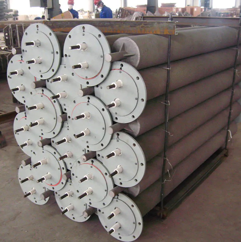
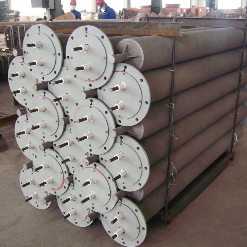
In the Huaye product range, radiant tubes are available as single straight lengths, as a W-type radiant tube where one burner supplies a long multi-pass continuous tube, and as custom-cast straight pipe for replacement projects. The W-type geometry is a popular choice when a single burner must feed a long tube with multiple passes, effectively tripling the radiating surface in a compact overhead footprint.
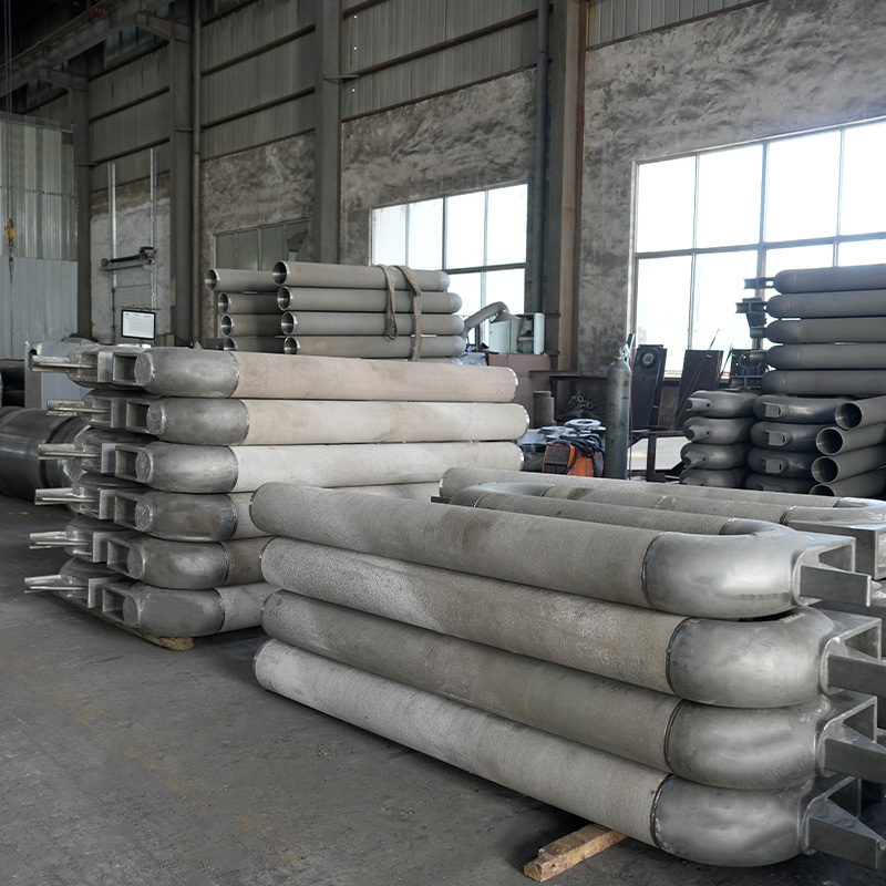 Wholesale W-Type Radiant Tube Manufacturer, Exporter CompanyJiangsu Huaye Technology Co., Ltd is China W-type radiant tube manufacturer and W-type radiant tube exporter company, We custom and whole...View Product →
The efficiency of a gas radiant tube heater is best measured as the fraction of input fuel energy that reaches the occupied zone as useful heat. In a well-installed heater that figure is typically 70% to 78%. By comparison, a forced-air unit heater with the same gas input delivers only 55% to 65% of its energy to the same space because a significant share collects at the ceiling in the form of stratification losses.
The radar chart compares a gas radiant tube heater with a forced-air unit heater across the six criteria that matter most to facility managers. Comfort scores 5 out of 5 for radiant because occupants receive direct infrared input, while forced air scores 3 because it relies on air movement to deliver warmth. Energy efficiency is 5 versus 2 for the reasons described earlier: stratification loss is almost absent in radiant systems. Indoor air quality is effectively equal, with radiant scoring 4 because there are no filters to maintain and forced air also scoring 4 when fitted with a proper heat exchanger. Noise is a clear advantage for radiant at 4 versus 2, as forced-air units are noticeably louder to generate the static pressure required to distribute air. Zoning flexibility is 5 versus 3 because each radiant heater is a self-contained zone with its own thermostat. Installation cost is the only criterion where forced air wins at 5 versus 3, although that difference is normally recovered within two heating seasons in any climate colder than about 2,000 heating degree-days.
Typical applications for gas radiant tube heaters include vehicle maintenance bays, airplane hangars, fire stations, factory floors, warehouses, distribution centers, greenhouses, and indoor sports facilities. The common denominator is a building with high ceilings, large door openings, or elevated ventilation rates. In these conditions, forced-air heat is lost to the roof every time a door opens, while radiant heat stays in the floor slab and re-releases gradually. A concrete floor with high thermal mass is the best match because it absorbs radiation during the day and re-emits it at night, flattening the temperature curve and reducing peak load at dawn.
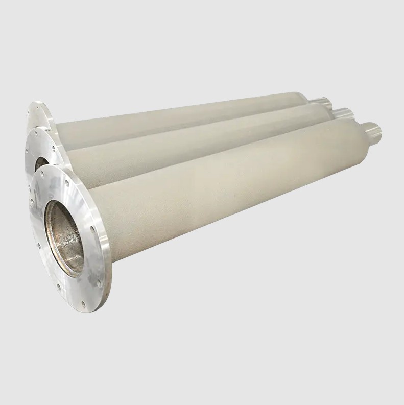
Correct sizing starts with a standard heat-loss calculation, not floor area rules of thumb. The calculation must include the building envelope, infiltration rate, open-door time per shift, and indoor design temperature. Oversizing a radiant tube heater produces short-cycling and uneven floor coverage, while undersizing forces the unit to run continuously and loses the benefit of cyclic re-radiation from the concrete floor. After the heat load is known, the selection variables are mounting height, which determines the reflector angle, tube length, which determines the width of the heated strip, and the number of heater passes. For installations where the gas supply can be positioned at one wall and the flue at the opposite wall, the I-shaped radiant tube offers the lowest cost per meter and the simplest construction, though it requires access at both ends.
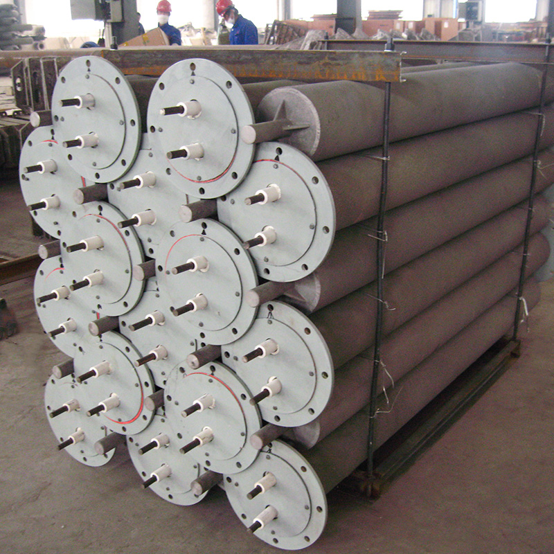 Wholesale I-Shaped Radiant Tube Manufacturer, Exporter CompanyJiangsu Huaye Technology Co., Ltd is China I-shaped radiant tube manufacturer and I-shaped radiant tube exporter company, We custom and w...View Product →
The bar chart compares the typical annual heating cost for a 2,000 square meter workshop in a location with 3,200 heating degree-days under four different heating technologies. The gas radiant tube heater produces an annual cost around 22,000 dollars, about 30% lower than the forced-air unit heater, which comes in near 31,000 dollars. Hydronic floor heating shows a cost slightly below the radiant tube system at around 20,000 dollars, but it requires a complete concrete floor reconstruction that few retrofit projects can justify. Electric resistance heating is by far the most expensive option at roughly 44,000 dollars because of the power-to-heat conversion economics. These figures are typical of well-insulated post-1980 buildings and become even more favorable for radiant tube heating when the building is poorly insulated or has frequent door cycling. The conclusion is that gas radiant tube heaters offer the most attractive combination of upfront cost, operating cost, and retrofit feasibility for most industrial buildings.
Before finalizing a purchase, verify that the burner controller supports the maintenance schedule your facility demands, check the clearance distances to combustible materials in the installation manual, and request a layout drawing from the supplier showing heater positions, gas train components, and vent terminations. If you share the building plans and insulation details with our application engineers, we can confirm the heater count and generate a preliminary spacing diagram for budgeting.
Gas radiant tube heaters work by converting the chemical energy of gas into infrared radiation through a sealed, heated metal tube. The direct nature of radiant heat transfer gives this technology its efficiency advantage in high-clearance buildings, and with correct sizing, tuning, and maintenance, a radiant tube system will provide comfortable floor-level heat season after season. If you are evaluating this technology for your facility, the practical next step is to calculate your heat loss, review the certified heater options, and request a layout proposal from an experienced manufacturer.
We will reply to you as soon as possible.
 custom alloys for sale
wholesale different alloys
custom alloys for sale
wholesale different alloys