No. 308, Gongxin Road, Industrial Park, Dongxing Town, Jingjiang City, Jiangsu Province, China
 [email protected]/ [email protected]
 English
 Español
 русский
 中文简体
中文简体 No. 308, Gongxin Road, Industrial Park, Dongxing Town, Jingjiang City, Jiangsu Province, China[email protected]/ [email protected]
Choosing the right Radiant Tube requires evaluating five core parameters: operating temperature, material composition, tube geometry (shape and dimensions), atmosphere compatibility, and furnace configuration. Get any one of these wrong and the result is premature tube failure, uneven heating of the workpiece, unplanned furnace downtime, or in the worst case a safety incident caused by tube rupture and combustion gas ingress into the furnace chamber. The decision is engineering-critical because a radiant tube operating in an industrial furnace may cycle thousands of times over a service life of 3 to 10 years, experiencing thermal gradients, oxidizing and carburizing atmospheres, and mechanical loads simultaneously. The sections below walk through each selection parameter in practical detail, with specific data and examples to anchor the decision process.
Content
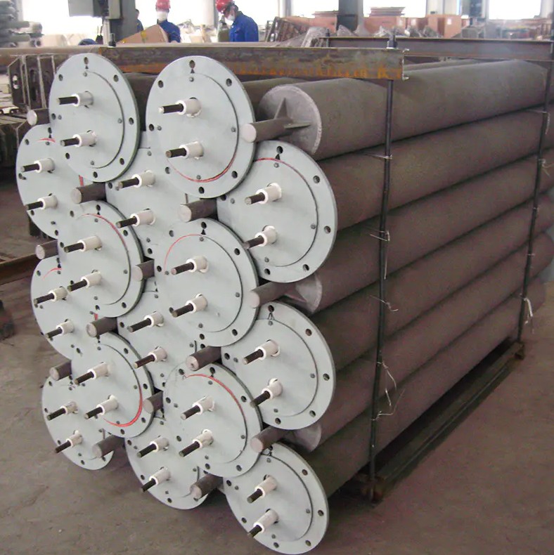
A radiant tube is a sealed combustion enclosure inserted through the wall of an industrial furnace. A gas burner fires inside the tube, and the combustion products travel through the tube's length — typically in a U, W, P, or straight configuration — before exiting through a flue at the other end. The tube wall absorbs the combustion heat and re-radiates it into the furnace chamber as infrared radiation, heating the workpiece without any contact between combustion gases and the furnace atmosphere. This separation is the fundamental purpose of the radiant tube: it allows a controlled, often protective atmosphere inside the furnace chamber while still using gas combustion as the heat source.
The tube wall is simultaneously exposed to combustion gases at up to 1,150 deg C or higher on the inner surface and to the furnace atmosphere — which may be reducing, carburizing, nitriding, or neutral — on the outer surface, while supporting its own weight and the weight of the burner assembly in a cantilevered or supported configuration. No other component in the furnace system operates under this combination of thermal, chemical, and mechanical demands simultaneously. This is why material selection is the most consequential choice in radiant tube specification.
The single most important parameter in radiant tube selection is the maximum operating temperature — specifically the tube wall temperature, not the furnace set-point temperature. The tube wall is always hotter than the furnace atmosphere because it is the primary heat source, and the local flame zone inside the tube may be significantly hotter than the average tube wall temperature indicated by a thermocouple.
In a well-designed radiant tube system, the tube wall temperature typically runs 50 to 150 deg C above the furnace set-point temperature. A furnace operating at 900 deg C may have a radiant tube wall temperature of 950 to 1,050 deg C at the hottest zone near the burner flame. Specifying a tube material rated exactly to the furnace set-point temperature without adding this margin is the most common cause of premature tube failure in service.
As a general framework for temperature band allocation:
| Furnace Set-Point Temperature | Typical Tube Wall Temperature | Minimum Material Temperature Rating |
|---|---|---|
| Up to 800 deg C | 850 to 950 deg C | 1,000 deg C |
| 800 to 950 deg C | 950 to 1,100 deg C | 1,150 deg C |
| 950 to 1,050 deg C | 1,050 to 1,200 deg C | 1,250 deg C |
| 1,050 to 1,150 deg C | 1,150 to 1,300 deg C | 1,350 deg C |
| Above 1,150 deg C | 1,250 to 1,400 deg C | Ceramic or SiC tube; nickel superalloy |
A radiant tube that reaches operating temperature once per day and holds steady experiences far less thermal fatigue than one that cycles from cold to operating temperature and back multiple times per shift. Thermal cycling generates cyclic thermal stress in the tube wall from differential expansion between the hot inner and cooler outer surface zones. High-cycling applications — such as batch annealing furnaces or hardening furnaces that load and unload frequently — require tube materials with superior thermal fatigue resistance, which typically means higher nickel content alloys or silicon carbide ceramics rather than iron-based alloys.
The ASTM standard for high-temperature service of heat-resistant alloys (ASTM A297 and A351) categorizes alloy grades by operating temperature and provides minimum property requirements that serve as a useful starting framework for material selection, though specific application requirements may justify exceeding these minimums (Source: ASTM International, Standard Specification for Steel Castings, Alloy, for High-Temperature Service, A297/A297M).
The chemical environment on both sides of the radiant tube wall determines which alloy families are appropriate. A tube that performs excellently in an oxidizing atmosphere may be rapidly attacked in a carburizing or sulfur-bearing atmosphere, and vice versa. Material-atmosphere compatibility is non-negotiable and must be established before any other selection parameter is finalized.
The furnace atmosphere contacting the outer tube surface varies by heat treatment process:
The combustion gases flowing inside the radiant tube are primarily CO2, H2O, N2, and excess O2 in the case of lean combustion, or CO, H2, and N2 in rich combustion zones. The inner surface is exposed to an oxidizing environment in lean combustion regions and a reducing or carburizing environment in fuel-rich zones near the burner nozzle. Locally rich combustion near the burner tip can produce a reducing zone that promotes carburization of the tube inner surface even when the overall air-to-fuel ratio is near-stoichiometric.
| Atmosphere Type | Primary Attack Mechanism | Recommended Alloy Family | Key Alloying Elements for Resistance |
|---|---|---|---|
| Oxidizing (air, lean combustion) | Surface oxidation; scale formation | Fe-Cr-Ni austenitic; Fe-Cr-Al | Cr above 20%; Al above 3% for FeCrAl |
| Carburizing (endogas, rich zones) | Carbon absorption; embrittlement | High Ni austenitic (above 35% Ni); HK40; HP-modified | Ni above 35%; Nb and W additions |
| Nitriding (dissociated ammonia) | Nitride phase formation; embrittlement | High Ni austenitic; Ni-base alloys | Ni above 40%; avoid high Cr ferritic grades |
| Sulfidizing (sulfur-bearing fuels) | Sulfidation; rapid metal loss | High Cr austenitic (above 25% Cr); Ni-Cr | Cr above 25%; avoid Co-based alloys |
| Reducing / hydrogen-rich | Oxide scale reduction; possible H embrittlement | Austenitic Fe-Ni-Cr; avoid ferritic grades | Ni above 20%; avoid delta ferrite in welds |
| Combined carburizing and oxidizing (cyclic) | Green rot; catastrophic oxidation at scale-metal interface | HP-modified alloys; SiC ceramic | Nb, W, Si above 1.5% for HP grades |
With operating temperature and atmosphere compatibility defined, the alloy grade can be selected from the standard families used in industrial radiant tube manufacture. Each family has specific strengths and limitations that determine its suitability for particular applications.
HK40 (Fe-25Cr-20Ni-0.4C) is the most widely used centrifugally cast alloy for radiant tubes in the temperature range of 900 to 1,050 deg C. Its relatively balanced composition provides good oxidation resistance from the chromium content, adequate creep strength from the 0.4% carbon level (which precipitates chromium carbides that impede dislocation movement at elevated temperature), and cost-effectiveness from its lower nickel content compared with higher-nickel grades. HK40 is the appropriate first choice for carburizing and neutral hardening furnaces where the operating temperature is within its capability range.
HK40's limitations become apparent above approximately 1,050 deg C, where its creep strength drops sharply, and in severely carburizing atmospheres where the lower nickel content (20%) relative to HP-grade alloys makes it more susceptible to carbon absorption leading to sigma phase embrittlement after extended service.
HP-modified alloys (Fe-25Cr-35Ni-0.4C with additions of Nb, W, Ti, or combinations) extend the operating temperature ceiling to 1,100 to 1,150 deg C and provide significantly better resistance to carburization than HK40 due to their higher nickel content. Niobium additions in HP-Nb grades precipitate stable NbC carbides that resist dissolution and maintain the alloy's creep strength over extended service. HP-modified grades are the standard choice for gas carburizing furnaces, high-temperature annealing furnaces, and any application where the tube wall temperature is expected to exceed 1,050 deg C in service.
For the most demanding applications — temperatures above 1,100 deg C, severely carburizing or sulfidizing atmospheres, or applications requiring exceptional thermal fatigue resistance — high-nickel alloys with nickel contents of 55 to 75 wt% provide performance that iron-based alloys cannot match. These materials are significantly more expensive than HK40 or HP grades, but in applications where iron-based alloys fail within 12 to 18 months and high-nickel alloys provide 4 to 7 years of service, the economics strongly favor the premium alloy despite its higher initial cost.
Silicon carbide ceramic radiant tubes operate at temperatures that are beyond the capability of any metallic alloy — up to 1,350 to 1,400 deg C tube wall temperature in continuous service. SiC has exceptional oxidation resistance (forming a protective SiO2 surface layer), very high thermal conductivity (approximately 3 to 5 times that of metallic alloys), and excellent resistance to carburization, nitriding, and sulfidation. The primary limitations of SiC radiant tubes are their brittleness — they cannot withstand mechanical shock or point loading that would crack the ceramic — and their higher cost compared with metallic alternatives at equivalent sizes.
SiC tubes are the standard choice for high-temperature continuous annealing lines, bright annealing of stainless strip, silicon steel processing, and any furnace where metallic tube replacement frequency has become unacceptably high due to temperature limitations.
Cast iron and low-carbon steel tubes are occasionally encountered in older or lower-cost furnace installations where operating temperatures are below 750 deg C and atmosphere requirements are minimal. Above this temperature, the rapid oxidation and growth of iron oxide scale on unalloyed or low-alloy steel makes these materials unsuitable for any radiant tube application where service life exceeding 6 to 12 months is expected. If a radiant tube specification proposes unalloyed or low-alloy steel for an operating temperature above 750 deg C, the specification requires revision before the installation proceeds.
Radiant tube geometry — the shape of the tube path through which combustion gases flow — directly affects heat distribution uniformity in the furnace, the tube's suitability for different furnace configurations, and the achievable heat input per tube. Four geometries are in common industrial use, each with specific advantages and appropriate applications.
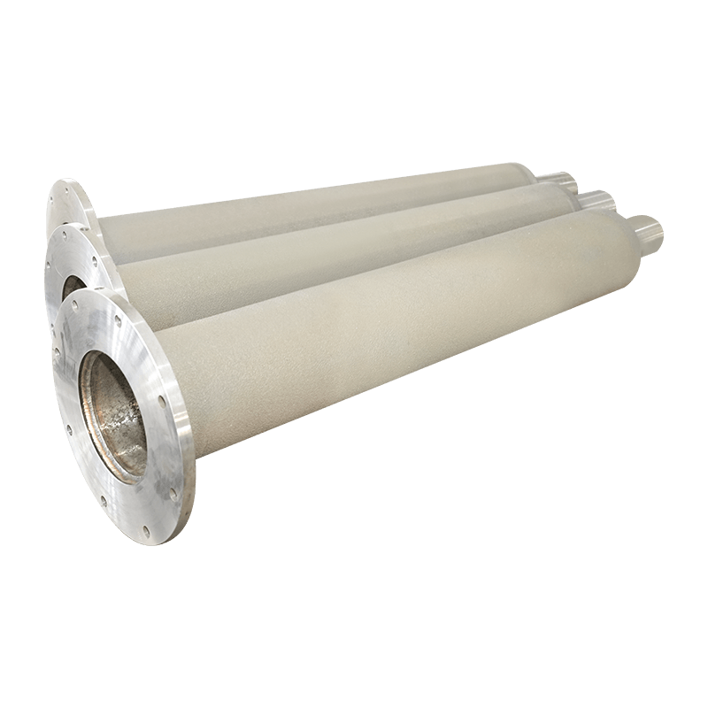
A straight radiant tube passes through the furnace wall on one side, spans the furnace chamber, and exits through the opposite wall. The burner fires from one end and flue gases exit from the other. Straight tubes provide excellent heat distribution along their length in horizontally or vertically oriented applications and are the simplest geometry to manufacture, install, and replace. They are appropriate for furnaces with sufficient interior width to accommodate the full tube length — typically 1,000 to 3,000 mm of heated length — and are standard in continuous strip annealing furnaces, wire annealing furnaces, and some batch furnaces.
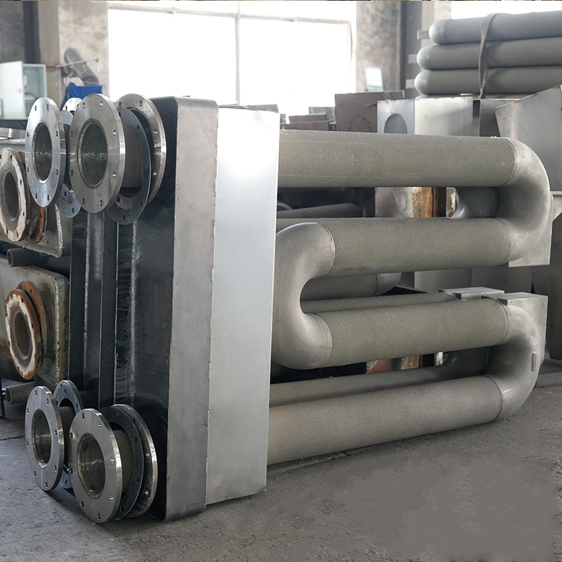
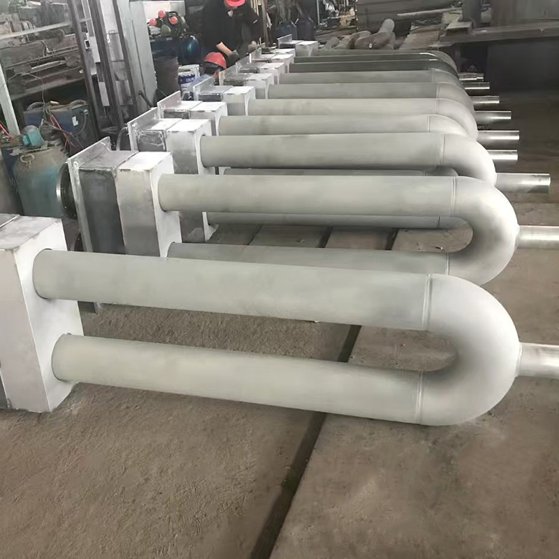
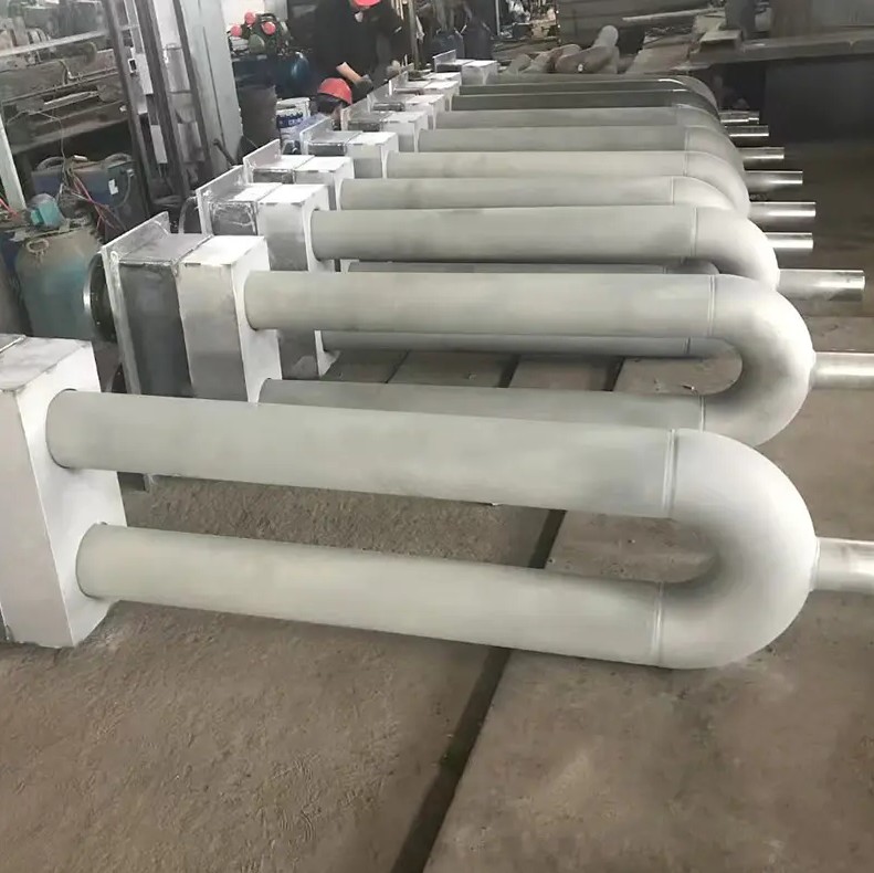
U-tubes consist of two parallel legs connected by a 180-degree bend at the closed end, with the burner and flue both accessible from the same furnace wall. The gas flows from the burner down one leg, around the U-bend, and back up the return leg to the flue exit. U-tubes are the most widely used geometry in batch furnaces, heat treatment furnaces, and any application where access from only one side of the furnace is practical. The primary design challenge with U-tubes is the temperature differential between the hot firing leg and the cooler return leg — the inner surface of the U-bend operates at a significantly higher temperature than the return leg average, creating a thermally stressed region that requires adequate wall thickness and material quality to resist creep deformation over service life.
W-tubes extend the U-tube concept by adding a second U-bend, creating a tube path that reverses direction twice within the furnace chamber before returning to the firing wall. W-tubes provide a longer heated path in a given furnace chamber depth, producing more heat input per furnace wall penetration than a U-tube of similar cross-section. They are used in applications where high specific heat input is required — such as high-productivity batch hardening furnaces — but their more complex geometry makes them more challenging to manufacture to dimensional tolerance and more difficult to replace in service.
P-tubes (also called elbow tubes or single-ended recirculating tubes) use an internal recirculating sleeve inside an outer tube body. The burner fires into the inner sleeve; combustion gases travel down the sleeve, reverse direction at the closed end, and flow back up the annular space between the sleeve and the outer tube to the flue exit at the burner end. The outer surface of the P-tube presents a more uniform temperature distribution than a U-tube because the hot inner sleeve preheats the return gases before they exit, reducing the temperature differential along the outer tube length. P-tubes are increasingly used in modern high-performance furnace designs where temperature uniformity across the heated zone is a primary requirement.
Within each geometry type, tube diameter and wall thickness are the primary dimensional parameters to specify:
The method by which the radiant tube body is manufactured has a direct impact on its metallurgical quality, dimensional precision, and high-temperature performance. Three manufacturing routes are used commercially, each with specific quality characteristics.
Centrifugal casting is the standard and preferred manufacturing method for metallic radiant tube straight sections and tube legs. Molten alloy is poured into a rotating mold; centrifugal force drives the liquid metal outward against the mold wall and keeps it there as it solidifies. The result is a tube with a dense, fine-grained outer zone (where centrifugal force is highest) and a progressively coarser grain zone toward the inner bore. Because the outer surface operates at lower temperature than the inner bore in a radiant tube, this grain structure gradient is ideally aligned with the stress distribution — the dense outer zone provides creep resistance where temperature is lower, and the coarser inner structure provides adequate strength without the excessive rigidity that fine grain structure would produce in the hotter inner zone.
Centrifugally cast tubes are consistently superior to static castings in high-temperature service. Research from the European Foundry Association (CAEF, Heat Resistant Alloy Casting Performance Data, 2019) confirmed that centrifugally cast HK40 tubes exhibited creep rupture lives approximately 40 to 60% longer than equivalent static castings of the same alloy composition tested at 1,000 deg C under the same stress levels, due to the denser and more uniform microstructure produced by centrifugal force during solidification.
Static (gravity) casting is used for U-bend sections, elbow components, and geometrically complex elements that cannot be produced by centrifugal casting. Static castings have inherently coarser microstructure, higher porosity, and more microstructural variability than centrifugal castings. They are acceptable for bend sections that operate at lower temperature than the tube legs, but should not be used for tube leg sections that will be exposed to the highest operating temperatures. When specifying a U-tube radiant tube, confirming that the straight leg sections are centrifugally cast and only the bend section is static cast is good engineering practice.
Wrought and welded radiant tubes — formed from rolled plate or extruded tube with longitudinal or circumferential welds — are occasionally used in lower-temperature applications (below 900 deg C) or in materials that are not amenable to casting, such as some dispersion-strengthened alloys. Welds in high-temperature alloys are a potential weak point because the weld heat-affected zone typically has lower creep strength than the base metal. In critical radiant tube applications above 900 deg C, cast tubes are preferred over welded fabrications for this reason.
The physical configuration of the furnace and the burner system being used constrains the radiant tube options available, and compatibility between tube and burner must be verified before tube ordering is finalized.
Horizontal radiant tube mounting — the most common configuration in continuous furnaces and many batch furnaces — subjects the tube to bending stress from its own self-weight and the weight of the burner assembly. The maximum bending stress occurs at the midspan of a straight tube or at the U-bend junction of a U-tube. For long horizontal spans exceeding approximately 1,500 to 2,000 mm in HK40 material, a support cradle at the midspan or selection of a thicker-walled tube may be necessary to limit creep sag over service life at operating temperature.
Vertical mounting (tube firing downward or upward through the furnace floor or roof) eliminates bending stress from self-weight but requires that the tube's end connections and flange systems are rated for the full weight of the tube in tension or compression rather than relying on the tube structure to carry bending loads. Vertical mounting is commonly used in bell furnaces, pot furnaces, and some continuous strip annealing lines.
The burner firing rate — expressed in kW or MBtu/hr — determines the heat flux through the tube wall. Exceeding the tube's maximum recommended thermal loading causes the inner surface to overheat above the alloy's creep capability, leading to accelerated sagging and eventual rupture. As a general guideline, standard metallic radiant tubes in HK40 or HP materials are designed for maximum heat flux densities of 60 to 90 kW/m2 of tube outer surface area. SiC tubes can sustain higher thermal loadings due to their superior thermal conductivity. Confirming that the proposed burner firing rate is within the tube's thermal loading limit for the specified diameter and length is a mandatory step in the selection process.
The radiant tube must interface mechanically with the burner assembly at the firing end and with the flue connection at the exit end. These connections are typically made through a mounting flange that engages with the furnace wall refractory or panel. Radiant tube flange designs vary by manufacturer and furnace builder, and the tube's connection end geometry must match the existing furnace mounting system. When replacing tubes in an existing furnace, obtaining the original tube drawing or a dimensional survey of the furnace wall mounting before ordering replacement tubes prevents costly dimensional mismatches that require furnace modification to resolve.
Understanding the most frequent radiant tube failure modes — and their root causes in selection or application errors — provides practical insight into which selection parameters matter most in each application context.
Creep sagging — the progressive downward deformation of a horizontal tube under self-weight at elevated temperature — is the most common failure mode in metallic radiant tubes. It occurs when:
Selection prevention: specify a material with an adequate safety margin on creep rupture stress at the maximum operating temperature, and verify that the tube dimensions produce acceptable bending stress at that temperature. Published creep data for heat-resistant alloys in ASTM A297 and in the AFS Heat Resistant Alloy Casting Manual provide the creep rupture stress values needed for this calculation.
Carburization — the absorption of carbon from the furnace atmosphere into the tube outer surface — occurs in all iron-chromium-nickel alloys to some degree in carburizing atmosphere furnaces. Severe carburization creates a high-carbon surface layer that is brittle and prone to cracking during thermal cycling. Over time, the carburized layer propagates inward, reducing the effective load-bearing wall thickness and causing progressive loss of creep resistance. Selection prevention: use HP-modified or high-nickel alloy grades in carburizing atmosphere furnaces; avoid HK40 where carburization resistance is the primary life-limiting factor.
Rapid oxidation leading to excessive scale formation and wall thinning occurs when a tube alloy is used above its maximum recommended oxidation temperature, or when the protective chromia or alumina scale is disrupted by thermal cycling, mechanical damage, or chemical attack. Scale spallation — the detachment of thick oxide layers during cooling — accelerates metal loss and can introduce oxide debris into the furnace atmosphere. Selection prevention: confirm that the alloy's maximum continuous oxidation temperature rating exceeds the tube wall temperature by a margin of at least 50 deg C.
Thermal fatigue cracks — typically initiated at the outer surface and propagating inward — result from the cyclic tensile and compressive stresses generated by repeated heating and cooling. They are most severe near geometric stress concentrations such as weld toes, U-bend junctions, and flange attachment points. High-cycling applications with multiple heat-cool cycles per shift accumulate fatigue damage faster than low-cycling applications. Selection prevention: in high-cycling applications, use higher-nickel alloys or SiC ceramic tubes with superior thermal fatigue resistance; avoid static cast bend sections in high-cycling duty.
Sulfidation attack — characterized by rapid scale formation with a layered sulfide-oxide structure and accelerated metal loss — occurs in furnaces processing sulfur-bearing workpieces or using sulfur-containing fuel gas. It is one of the most rapid and destructive failure modes for radiant tubes; a tube failing by sulfidation may lose 2 to 5 mm of wall thickness per year compared with less than 0.5 mm per year in oxidation-only service. Selection prevention: identify any sulfur source in the process before selecting the tube alloy, and specify high-chromium (above 25 wt%) alloys if sulfur is present at any meaningful concentration.
The following checklist consolidates the selection process into a structured sequence of questions that should be answered before finalizing a radiant tube specification. Each question links to the selection parameters discussed above.
The Radiant Tube series manufactured by Casting Huaye covers centrifugally cast straight sections, U-tubes, W-tubes, and static cast bend components in HK40, HP-modified grades, and high-nickel alloys, with technical support for application-specific material and geometry selection based on furnace temperature, atmosphere, and operating cycle data.
Radiant tube selection decisions made on initial purchase cost alone consistently produce higher total costs over the furnace maintenance cycle than decisions made on total cost of ownership (TCO). Understanding the cost drivers in each scenario is essential for making a business case for premium alloy selection when initial cost pressure is high.
The total cost of operating a radiant tube system over a maintenance period includes:
Consider a batch carburizing furnace operating at 940 deg C with 20 U-type radiant tubes. HK40 tubes provide 2 years of service life in the carburizing atmosphere; HP-modified tubes provide 5 years. If the cost of HK40 tubes is 60% of the HP-modified tube cost per set, and each tube replacement requires 16 hours of maintenance labor plus 2 days of furnace downtime at a production value of USD 15,000 per day:
In most industrial heat treatment scenarios, the total cost of ownership calculation favors selecting the highest-performance tube material that is technically appropriate for the operating conditions, rather than the lowest-cost option, because the downtime and labor cost of additional replacement events far exceeds the initial price premium of a longer-life material.
We will reply to you as soon as possible.
 custom alloys for sale
wholesale different alloys
custom alloys for sale
wholesale different alloys