No. 308, Gongxin Road, Industrial Park, Dongxing Town, Jingjiang City, Jiangsu Province, China
 [email protected]/ [email protected]
 English
 Español
 русский
 中文简体
中文简体 No. 308, Gongxin Road, Industrial Park, Dongxing Town, Jingjiang City, Jiangsu Province, China[email protected]/ [email protected]
Modern industrial Radiant Tube systems operating in heat treatment furnaces achieve thermal efficiencies of 40 to 75% depending on tube configuration, burner technology, furnace design, and whether a heat recovery system is integrated. With recuperative or regenerative burner systems, the upper end of this range extends to 75 to 85% — making recuperated radiant tube furnaces among the most thermally efficient configurations available for indirect gas-fired heating in controlled-atmosphere applications. (Source: Industrial Heating Equipment Association, Combustion Efficiency Guidelines; North American Combustion Handbook, 3rd Edition, 1986.)
The efficiency of a radiant tube is not a fixed number — it is a dynamic performance characteristic determined by the interplay of combustion efficiency, tube wall emissivity, flue gas heat recovery, furnace geometry, and operating temperature. Understanding each of these variables, and how they interact, is essential for specifying, operating, and maintaining radiant tube heating systems at their maximum productive potential. The sections below examine every significant dimension of radiant tube efficiency in detail, with specific data and operational examples to support each point.
Content
A radiant tube is an indirect gas-fired heating element — typically a sealed alloy steel or ceramic tube through which a burner flame passes — used in controlled-atmosphere furnaces to heat workpieces without exposing them to combustion products. The tube absorbs combustion heat from the internal flame and radiates it outward to the furnace chamber and the load, maintaining the controlled atmosphere (nitrogen, hydrogen, endothermic gas, or other protective atmospheres) that the heat treatment process requires.
The efficiency question is central to radiant tube selection and operation for two interconnected reasons. First, fuel cost: natural gas combustion is the single largest operating cost in most heat treatment facilities, and thermal efficiency directly determines gas consumption per unit of heat delivered to the load. A facility operating 10 radiant tube furnaces at 50% thermal efficiency rather than 70% efficiency consumes 40% more gas for the same production output — a cost differential that compounds dramatically at industrial scale over a year of operation. Second, tube service life: operating efficiency influences the temperature distribution and peak temperatures within the tube, which directly determines tube material degradation rate and replacement frequency.
(Source: U.S. Department of Energy, Energy Tips — Process Heating: Improve Your Combustion System; IHEA Combustion Technology Manual.)
Radiant tube thermal efficiency is defined as the ratio of heat delivered to the furnace atmosphere and load to the total heat released by combustion of the input fuel. It is expressed as:
Thermal Efficiency (%) = (Heat Input - Flue Gas Heat Loss - Other Losses) / Heat Input x 100
The dominant loss mechanism in any gas-fired radiant tube system is the heat carried away in the exhaust (flue) gases leaving the tube. In a simple straight-through radiant tube without any heat recovery, flue gas temperatures at the tube exit commonly reach 800 to 1,100 degrees C at furnace operating temperatures of 900 to 1,150 degrees C — representing a substantial fraction of the original combustion heat being discharged unused into the stack. This is the primary efficiency challenge that radiant tube system designers address through recuperation, regeneration, and tube geometry optimization.
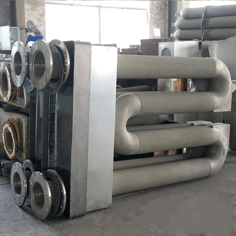
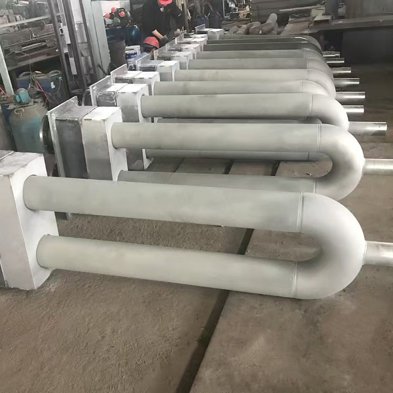
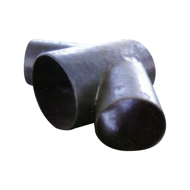
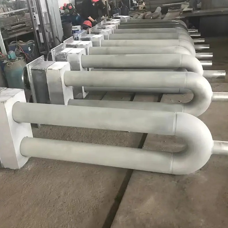
The geometric configuration of the radiant tube — straight, U-tube, P-tube, W-tube, or single-ended recuperative (SER) — is the primary structural variable that determines baseline thermal efficiency before any heat recovery is applied. Each configuration distributes the flame and combustion products differently through the tube length, affecting heat transfer uniformity and flue gas exit temperature.
| Tube Configuration | Typical Efficiency Range | With Recuperation | Primary Application |
| Straight-through (I-tube) | 35 to 45% | 55 to 65% | Simple furnace geometries; low-profile configurations |
| U-tube (double-pass) | 45 to 55% | 60 to 70% | Continuous belt furnaces; roller hearth furnaces |
| P-tube (triple-pass) | 50 to 58% | 63 to 72% | High-temperature processes requiring extended heat transfer length |
| W-tube (quad-pass) | 52 to 62% | 65 to 75% | Batch furnaces; pusher furnaces with wide hearths |
| Single-Ended Recuperative (SER) | 55 to 65% | 70 to 85% (integral recuperation) | High-efficiency installations; new furnace builds where maximum efficiency is specified |
The efficiency advantage of U, P, and W-tube configurations over straight-through tubes comes from the increased residence time of hot combustion gases within the tube before exhaust. In a straight-through tube, hot combustion products travel the tube length once before exiting. In a U-tube, the same gases are redirected back through a parallel return leg, effectively doubling the time available for heat transfer to the tube wall. Each additional pass extracts more heat from the same combustion gases before they reach the flue stack.
The thermodynamic consequence is a measurably lower flue gas exit temperature per unit of tube length. A W-tube configuration with the same burner input and furnace temperature as a straight-through tube typically achieves flue gas exit temperatures 150 to 250 degrees C lower than the straight configuration — directly translating that temperature difference into recovered heat delivered to the furnace rather than exhausted to the stack. (Source: Flanagan, P.J., "Radiant Tubes — A Review," Journal of the Iron and Steel Institute, 1970; Steel Technology International Annual Review.)
The single-ended recuperative (SER) radiant tube represents the highest efficiency standard achievable in conventional radiant tube technology. In an SER configuration, the burner and flue outlet are both located at the same end of the tube — the burner fires down a central inner tube, combustion products reverse at the blind end and return through the annular outer space surrounding the inner tube, during which they pre-heat the incoming combustion air through the wall of the inner tube before exiting at the burner end. This integral recuperation recovers a significant fraction of flue gas heat and returns it to the combustion air, reducing the fuel required to sustain a given flame temperature.
SER tubes with high-performance metallic recuperators pre-heat combustion air to 400 to 650 degrees C before mixing with fuel at the burner — a combustion air preheat that improves net thermal efficiency by 15 to 25 percentage points compared to the same tube geometry operating with ambient-temperature combustion air. (Source: WS Warmeprozesstechnik GmbH, "Self-Recuperative Burner Systems for Radiant Tubes," Heat Treatment of Metals, 2003; Gas Processors Association Engineering Data Book.)
Thermal efficiency of the overall radiant tube system begins with combustion efficiency — the completeness with which the chemical energy in the fuel gas is released as heat by the burner flame within the tube. Poor combustion efficiency upstream of the tube reduces the heat available for transfer to the tube wall regardless of how well the tube geometry is optimized.
The combustion efficiency of a gas burner is critically dependent on the air-to-fuel ratio at the point of combustion. Stoichiometric combustion — the theoretically perfect ratio at which all fuel carbon and hydrogen is oxidized with exactly the oxygen available — releases the maximum heat per unit of fuel. In practice, burners operate with a small excess of air (typically 5 to 15% excess air for premix burners in radiant tube applications) to ensure complete combustion and avoid carbon monoxide formation.
The efficiency penalty for excess air is straightforward: every cubic meter of excess air not required for combustion is still heated by the flame and must exit the tube as hot exhaust, carrying with it heat that contributed nothing to combustion chemistry. At 10% excess air, the combustion efficiency penalty is modest — approximately 1 to 2 percentage points at furnace temperatures below 1,000 degrees C. At 30% excess air — a common result of poorly set or deteriorated burner control systems — the penalty rises to 4 to 8 percentage points, a significant and entirely avoidable efficiency loss. (Source: U.S. Department of Energy, Combustion Efficiency Calculations, Energy Efficiency and Renewable Energy Factsheet.)
The practical tool for maintaining combustion efficiency in radiant tube systems is continuous monitoring of the flue gas oxygen content at the tube exit using a calibrated zirconium oxide oxygen analyzer. Target oxygen content in flue gases from a well-tuned radiant tube burner is 1.5 to 3.5% O2 by volume — indicating slightly lean (excess air) combustion without significant oxygen waste. Systems with automated oxygen trim control — where the fuel-to-air ratio is continuously adjusted to maintain target flue gas oxygen — consistently achieve higher combustion efficiency than manually set systems and recover the additional efficiency value of precise air-fuel control.
The burner design used in a radiant tube profoundly affects both combustion efficiency and heat distribution along the tube length. High-velocity burners that direct the flame axially down the tube achieve high turbulence and rapid mixing, promoting complete combustion within a short flame length. Low-NOx burners using staged combustion (fuel-rich primary zone followed by secondary air injection) lengthen the flame and distribute heat more uniformly along the tube, reducing peak hot-spot temperatures that accelerate tube material degradation — improving both thermal uniformity and tube service life, though sometimes at a small combustion efficiency cost in the 1 to 2 percentage point range. (Source: Baukal, C.E., "Industrial Burners Handbook," CRC Press, 2003.)
Heat recovery from radiant tube exhaust gases is the most impactful single intervention for improving overall system efficiency. Two principal heat recovery technologies are applied to radiant tube systems: recuperative systems (which transfer heat from the flue gas to the incoming combustion air continuously through a metallic heat exchanger) and regenerative systems (which use alternating hot pebble-bed or ceramic matrix stores to absorb and release exhaust heat in timed cycles).
A recuperative radiant tube burner incorporates a metallic heat exchanger — typically constructed from high-temperature alloy steel or silicon carbide — through which the hot exhaust gases pass on their way to the stack and the incoming combustion air passes in the opposite (counter-flow) direction. This counter-flow heat exchange pre-heats the combustion air before it enters the burner, reducing the fuel energy required to reach the flame temperature needed for the process.
The efficiency gain from recuperation is directly related to the combustion air preheat temperature achieved:
(Source: Thekdi, A. and Nimbalkar, S.U., "Industrial Waste Heat Recovery — Potential Applications," U.S. Department of Energy Office of Energy Efficiency and Renewable Energy, 2014.)
The practical upper limit of metallic recuperator preheat temperature is constrained by the high-temperature mechanical properties of the recuperator material — standard austenitic stainless steel recuperators are limited to approximately 700 degrees C flue gas inlet temperature; silicon carbide ceramic recuperators can handle inlet temperatures up to 1,300 degrees C for high-temperature furnace applications.
Regenerative radiant tube burners use pairs of burners firing alternately — while one burner fires through its radiant tube, the flue gas from the opposite end is drawn through a ceramic pebble bed or honeycomb matrix that absorbs the exhaust heat. When the firing cycle reverses, the fresh combustion air for the newly firing burner passes through the hot ceramic bed, absorbing the stored exhaust heat and entering the combustion zone at very high temperature.
Regenerative systems achieve higher combustion air preheat temperatures than recuperative systems — typically 800 to 1,000 degrees C preheat at furnace temperatures of 1,000 to 1,200 degrees C — delivering fuel savings of 40 to 55% compared to cold-air combustion at equivalent process conditions. This makes regenerative radiant tube systems the highest-efficiency configuration available for high-temperature continuous heat treatment operations. The trade-off is increased capital cost, more complex control systems, and higher maintenance requirements for the switching valve assemblies and ceramic bed media that are unique to regenerative burner systems. (Source: Patel, N. et al., "Regenerative Burner Technology for Heat Treatment Furnaces," Thermal Processing Magazine, 2015.)
The material from which a radiant tube is constructed affects efficiency through two mechanisms: the emissivity of the tube surface (which determines how effectively it radiates heat to the furnace load) and the tube's thermal conductivity and maximum operating temperature (which determine how much heat can be transferred through the tube wall before material degradation limits operating intensity).
A radiant tube transfers heat to its surroundings primarily by thermal radiation — electromagnetic energy emission from the hot tube surface to the cooler furnace walls and workpieces. The efficiency of this radiation transfer is governed by the tube surface emissivity (epsilon), a dimensionless value between 0 and 1 where 1 represents a perfect blackbody radiator.
The radiated heat flux from the tube surface is described by the Stefan-Boltzmann law:
Q = epsilon x sigma x A x (T_tube to the power 4 - T_furnace to the power 4)
Where sigma is the Stefan-Boltzmann constant (5.67 x 10 to the power -8 W/m2K4), A is the tube surface area, T_tube is the absolute tube surface temperature, and T_furnace is the absolute furnace temperature. The fourth-power temperature dependence means that even small increases in tube surface temperature produce large increases in radiated heat flux — and that emissivity, which multiplies the entire radiation term, has a direct and linear effect on radiated power output. (Source: Incropera, F.P. et al., "Fundamentals of Heat and Mass Transfer," 7th Edition, Wiley, 2011.)
| Tube Material | Emissivity (epsilon) at Operating Temperature | Max Operating Temperature | Key Properties |
| HK40 (25Cr-20Ni) | 0.80 to 0.88 | 1,050 degrees C | Good oxidation resistance; widely used; moderate cost |
| HP (25Cr-35Ni-Nb) | 0.82 to 0.90 | 1,100 degrees C | High creep resistance; excellent for high-temperature continuous service |
| 35Cr-45Ni alloy | 0.83 to 0.91 | 1,150 degrees C | Premium oxidation and carburization resistance; extended service life |
| Silicon Carbide (SiC) | 0.85 to 0.93 | 1,400 degrees C | Highest temperature capability; excellent emissivity; brittle — requires careful handling |
| Mullite / Alumina ceramic | 0.82 to 0.90 | 1,350 degrees C | Excellent chemical resistance; suitable for reactive atmosphere furnaces |
Emissivity is not a fixed property of a tube material — it changes with surface condition over time. A freshly manufactured alloy radiant tube develops a chromium oxide scale layer on its surface during initial high-temperature operation (a process called conditioning or seasoning) that actually increases emissivity compared to the polished as-manufactured surface. This scale layer — typically 10 to 50 micrometers thick — has emissivity values in the 0.85 to 0.92 range, higher than the underlying alloy metal surface of 0.70 to 0.80. Properly conditioned alloy radiant tubes therefore radiate more efficiently than new, unconditioned tubes — a counter-intuitive finding that underscores the importance of correct commissioning procedures.
However, as tubes age, scale growth continues beyond the optimal protective layer and begins to flake, and internal carburization and oxidation degrade the tube wall. Heavily scaled, internally carburized tubes can develop reduced effective wall thermal conductivity that impairs heat transfer from the combustion side to the radiating outer surface, partially offsetting the emissivity advantage of the developed scale layer.
The uniformity of temperature distribution along the radiant tube length is both an efficiency parameter and a quality parameter. Non-uniform temperature distribution wastes available tube surface area for heat transfer and creates thermal stress concentrations that accelerate tube material degradation.
In a straight-through (single-pass) radiant tube, the flame from the burner is hottest immediately downstream of the burner tip, producing a localized hot zone in the first 20 to 30% of the tube length where the temperature significantly exceeds the rest of the tube. This hot zone can reach temperatures 100 to 200 degrees C above the average tube surface temperature, creating a region of intense thermal stress and accelerated oxidation and creep that is the most common initiation point for radiant tube failure in single-pass configurations.
The hot zone also represents a form of efficiency waste — the extremely high temperature of this zone drives very high radiation intensity locally, but the bulk of the tube length below the hot zone is significantly cooler than necessary for efficient heat transfer. The total heat transfer from the tube is therefore less uniformly distributed than the same heat input would produce in a multi-pass or low-NOx staged-combustion configuration.
Low-NOx burner technology, originally developed to reduce nitrogen oxide emissions from gas combustion, has the beneficial side effect of producing more uniform temperature distribution along the tube length. By staging the combustion — burning the fuel in two or three sequential zones along the tube rather than in a concentrated primary flame — the peak temperature is reduced and heat release is spread over a longer tube length. In radiant tube applications, this produces:
(Source: Baukal, C.E. and Waibel, R.T., "NOx Handbook for the Metals Industry," Gas Research Institute Technical Report; American Gas Association Laboratories.)
The efficiency delivered by a radiant tube system depends not only on the tube and burner design but on how the tube array is integrated into the furnace structure. Several furnace design factors significantly influence system thermal efficiency.
The view factor between the radiant tube array and the furnace load — the geometric parameter that describes what fraction of radiation leaving the tube surface reaches the load directly — determines how efficiently the tube's radiated energy heats the workpiece. Tubes spaced too widely leave large areas of furnace sidewall directly exposed to the load, causing the load to exchange radiation with the cooler furnace wall rather than the hot tube surface. Tubes spaced too closely block each other's view of the load (tube-to-tube radiation exchange) and waste tube surface area on heating adjacent tubes rather than the workpiece.
Optimal tube spacing in a radiant tube furnace is typically determined by the tube outer diameter (OD) and the furnace height. A common design rule is to space tubes at a center-to-center distance of 2 to 3 times the tube OD when tubes are mounted on furnace sidewalls, with the load positioned at a distance approximately equal to 1 to 1.5 times the tube spacing from the tube face. This geometry maximizes the combined view factor of the tube array to the load while maintaining adequate combustion air and fuel supply access. (Source: Trinks, W. and Mawhinney, M.H., "Industrial Furnaces," Volume 1, 6th Edition, Wiley, 2003.)
Furnace wall insulation quality directly affects system efficiency through two mechanisms. Poor insulation causes significant heat loss through the furnace walls and roof — heat that is generated by the radiant tubes but exits through the structure rather than heating the load. This wall loss is a direct efficiency deduction from the heat delivered by the tubes. Ceramic fiber insulation in modern furnace construction achieves wall heat flux values of 500 to 1,500 W/m2 at operating temperature, compared to 3,000 to 6,000 W/m2 for older brick-insulated furnace walls — a reduction in wall heat loss of 60 to 75% that translates directly into improved overall system efficiency.
Furnace thermal mass — the heat energy stored in the furnace walls and structure that must be supplied before the furnace reaches operating temperature from cold — affects efficiency primarily in batch furnace operations with frequent heat-up cycles. High-thermal-mass brick furnaces require significantly more fuel energy per cycle to bring the furnace to temperature than low-thermal-mass ceramic fiber-insulated designs. For batch operations with more than one heat-up per shift, the fuel energy consumed in heating the furnace structure can represent 10 to 20% of total fuel consumption — a component of efficiency that is often overlooked in system comparisons that focus only on steady-state operating efficiency.
The efficiency of heat recovery from flue gases is also affected by the duct design between the radiant tube exhausts and the recuperator or stack. Long, uninsulated flue gas ducts allow the hot exhaust to cool before reaching the recuperator, reducing the available temperature driving force for air preheat and wasting heat to the environment. Well-designed systems insulate flue gas ducting with ceramic fiber or mineral wool, minimizing duct heat loss and preserving flue gas temperature for maximum recuperation effectiveness.
Radiant tube efficiency is not static — it changes continuously throughout the operating life of the tube and burner system. Systematic monitoring and preventive maintenance are essential to prevent efficiency from drifting downward from its design value as equipment ages and process conditions change.
The following measurable parameters provide real-time and periodic assessment of radiant tube system efficiency:
The following scheduled maintenance actions maintain radiant tube system efficiency at or near design values throughout the tube service life:
Understanding radiant tube efficiency requires context — how does it compare to the alternative heating technologies that compete with it in industrial heat treatment applications?
| Heating Technology | Typical Thermal Efficiency | Atmosphere Compatibility | Temperature Ceiling |
| Radiant Tube (no recovery) | 35 to 62% | Full controlled atmosphere compatibility | Up to 1,150 degrees C (alloy); 1,400 degrees C (SiC) |
| Radiant Tube (with recuperation) | 60 to 85% | Full controlled atmosphere compatibility | Up to 1,150 degrees C (alloy); 1,400 degrees C (SiC) |
| Direct-Fired Gas (open flame) | 40 to 70% (with recuperation) | Not compatible — combustion products contact load | Above 1,400 degrees C possible |
| Electric Resistance Heating | 85 to 95% (electrical input to heat) | Full controlled atmosphere compatibility | Up to 1,800 degrees C with appropriate elements |
| Electric Induction Heating | 55 to 75% (including power electronics losses) | Compatible with vacuum and protective atmospheres | Above 1,200 degrees C with appropriate coil design |
Electric resistance heating achieves higher point-of-use efficiency than gas-fired radiant tubes when measured on an electrical input basis. However, when primary energy efficiency is considered — accounting for the efficiency losses in electrical power generation and transmission (typically 35 to 40% generation efficiency for grid-average fossil fuel power plants) — the primary energy efficiency of electric resistance heating at the generation level is only 30 to 35%, compared to 60 to 85% for recuperated gas-fired radiant tubes at the point of fuel combustion. In markets with high renewable electricity penetration, this primary energy comparison changes favorably for electric heating — an increasingly important consideration as grids decarbonize. (Source: IEA World Energy Outlook; EPA Power Generation Efficiency Data.)
For controlled-atmosphere heat treatment applications — carburizing, carbonitriding, neutral hardening, annealing, and tempering — the radiant tube remains the preferred combination of atmosphere compatibility and gas-fired efficiency, with recuperated configurations delivering primary energy efficiency that approaches electric resistance heating when source energy accounting is applied.
For facilities operating existing radiant tube furnaces that have not been optimized for maximum efficiency, the following measures offer the most significant and cost-effective improvements, ranked by typical payback period.
Cost of implementation: low. Payback period: immediate. A single combustion analysis measurement and burner adjustment session, using a portable flue gas analyzer calibrated to measure O2, CO, CO2, and combustion efficiency simultaneously, can recover 5 to 15% of fuel consumption in systems that have been operating with poor air-fuel control. This is the most accessible and fastest-payback efficiency intervention available and should be the first action in any radiant tube efficiency improvement program.
Cost of implementation: moderate to high (USD 15,000 to 80,000 per tube depending on size and configuration). Payback period: 12 to 36 months at typical industrial natural gas prices. Installing a recuperative burner system on a previously non-recuperated radiant tube can reduce fuel consumption by 20 to 35% at operating temperatures of 900 to 1,050 degrees C. For furnaces with many radiant tube burners (8 to 20 burners per furnace is typical for continuous belt or roller hearth designs), the aggregate fuel saving is substantial and payback periods are correspondingly short.
Air infiltration into furnace chambers through door seals, electrode ports, thermocouple penetrations, and conveyor openings causes two efficiency penalties: it dilutes the controlled atmosphere (increasing atmosphere gas consumption) and it introduces cold air that the radiant tubes must heat, increasing fuel consumption for no productive output. Systematic sealing of air infiltration paths — using ceramic fiber rope seals on doors, purge seals on conveyor openings, and mineral wool packing on instrument penetrations — can reduce fuel consumption by 5 to 12% in older furnaces with deteriorated sealing.
Replacing deteriorated refractory brick with ceramic fiber module insulation on furnace walls and roof reduces steady-state wall heat loss and thermal mass simultaneously, improving both continuous operating efficiency and batch cycle efficiency. For furnaces more than 15 to 20 years old with original brick insulation, insulation upgrades typically achieve fuel savings of 15 to 25% with payback periods of 2 to 5 years depending on furnace size and operating hours. (Source: DOE Industrial Technologies Program, "Waste Heat Reduction and Recovery for Improving Furnace Efficiency"; IHEA Technical Bulletin on Furnace Insulation.)
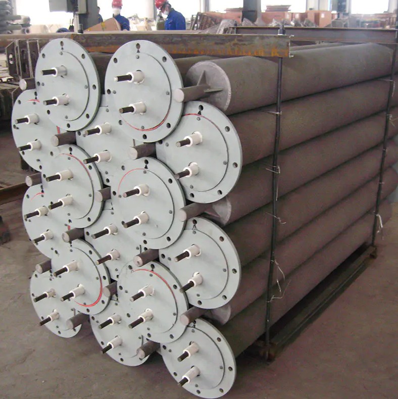
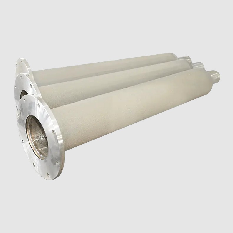
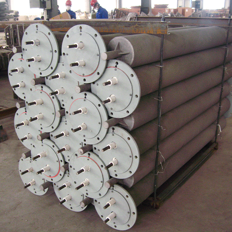
Our Radiant Tube product range is designed and manufactured with thermal efficiency and service life as co-equal engineering priorities. Every tube in our series is produced from carefully selected high-chromium nickel alloys — including HK40, HP modified, and 35Cr-45Ni grades — with composition control and casting quality optimized for the high surface emissivity, low internal oxidation rate, and creep resistance that maximize both radiation efficiency and service life in demanding continuous furnace environments.
The key engineering features of our radiant tube series that support operational efficiency include:
Whether the application is a high-volume continuous automotive carburizing line where fuel cost per unit processed is the primary economic metric, a precision aerospace hardening furnace where temperature uniformity is the dominant requirement, or a specialty ceramic sintering furnace operating at the maximum temperature capability of SiC tube technology, our radiant tube series provides the material quality and geometric precision needed to operate at peak efficiency throughout the tube's service life.
We will reply to you as soon as possible.
 custom alloys for sale
wholesale different alloys
custom alloys for sale
wholesale different alloys