Content
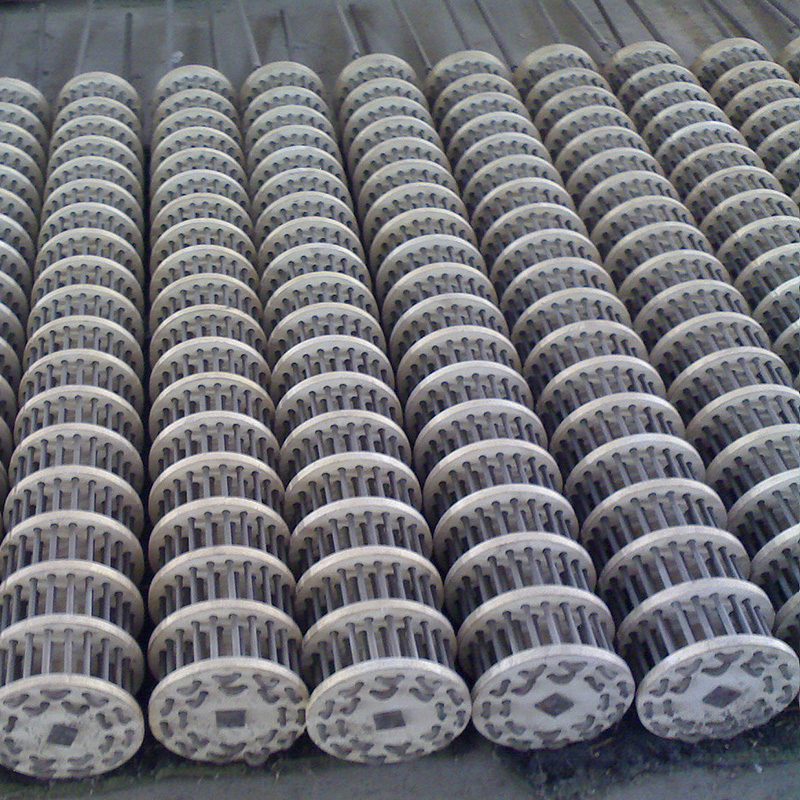
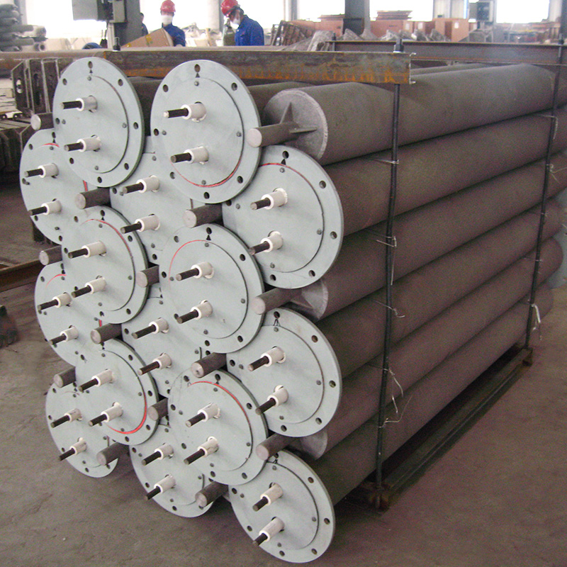
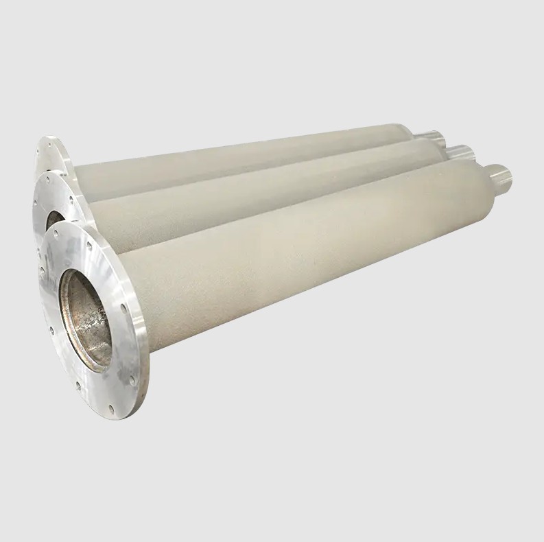
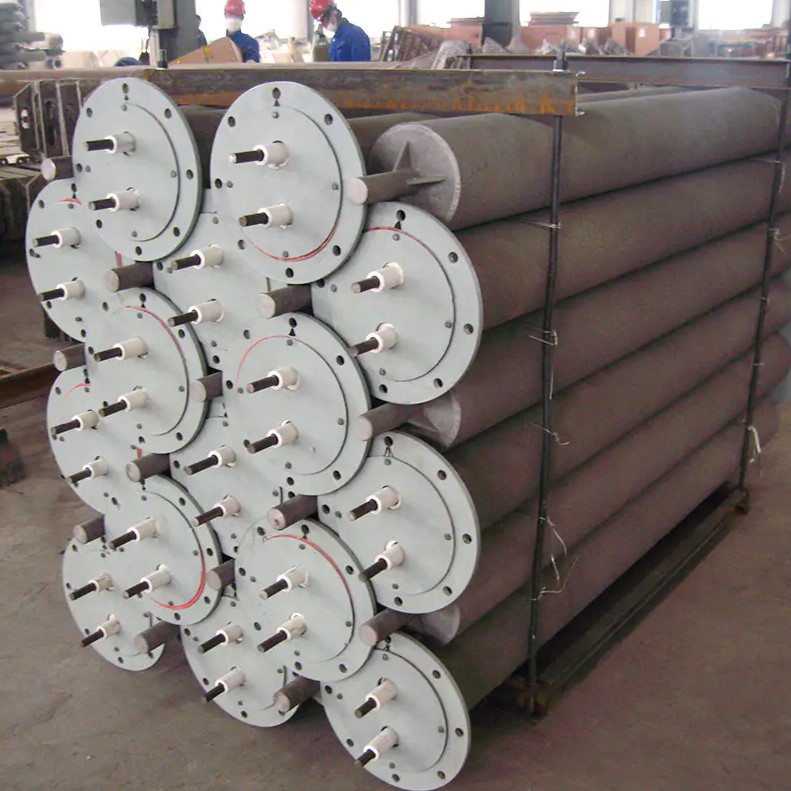
Radiant Tubes are high-temperature, indirect heating elements commonly used in industrial furnaces and heat treatment processes. They consist of a heating source (such as a gas burner or electric heating element) enclosed within a protective, heat-resistant tube, which radiates heat to the furnace interior while shielding the heating source from corrosive atmospheres.
Key Functions
Heat Transfer: Primarily through radiation (infrared), with a minor convective component, allowing for uniform heating of surfaces.
Protection: The tube protects the heating source from corrosive or oxidizing environments, extending the lifespan of the heating element.
Radiant tubes vary primarily in shape and design, each optimized for specific applications and space constraints.
| Type | Shape / Design | Typical Heat Transfer Surface | Common Applications | Pros | Cons |
|---|---|---|---|---|---|
| Straight | Linear, simple pipe | Limited to the tube's length | Small furnaces, simple designs | Easy to install and maintain | Lower heat transfer efficiency |
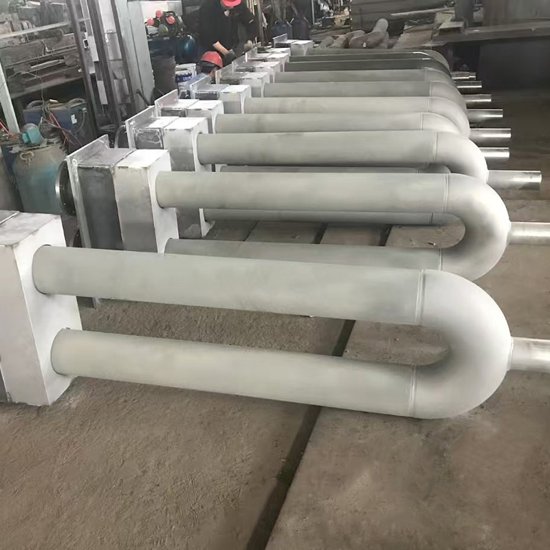
| U-Type | U-shaped bend | Increased surface area within a compact footprint | Belt furnaces, limited space | Better space utilization than straight | More complex to fabricate |
| W-Type | W-shaped with multiple bends | High surface area, excellent for large or wide heating zones | Large batch furnaces, plate heating | Maximizes heat distribution | Higher pressure drop, complex installation |
| P-Type | P-shaped with a loop | High surface area, often used for recirculating designs | High-temperature processes requiring uniformity | Efficient heat transfer | More complex to clean and maintain |
| Electric Heating Radiant Tubes | Varies (often straight or coil) | Depends on design, often lower temperature range | Small-scale or precise temperature control | Precise temperature control, no combustion gases | Limited to lower temperature ranges compared to gas-fired tubes |
The tube material is critical for performance, especially under high temperatures and corrosive atmospheres. Materials are chosen based on temperature resistance, corrosion resistance, and mechanical strength.
| Material | Composition | Typical Max Temperature | Key Properties | Typical Applications |
|---|---|---|---|---|
| Fe-Cr-Al Alloys | Iron, Chromium, Aluminum | Up to -1,200°C (2,192°F) | Excellent oxidation resistance, good mechanical strength | General-purpose high-temperature furnaces |
| Nickel-Based Alloys | High Nickel content, Chromium, Molybdenum | Up to -1,300°C (2,372°F) | Superior corrosion resistance, especially in reducing atmospheres | Highly corrosive or aggressive furnace environments |
| Heat-Resistant Casting Alloys | Various alloy compositions (often proprietary) | Varies (often >1,200°C) | Customizable for specific processes | Specialized industrial processes |
| Stainless Steel (Low-Carbon) | Iron, Chromium (18-20%) | Up to -1,000°C (1,832°F) | Good corrosion resistance, lower cost | Lower temperature applications |
When evaluating radiant tubes, buyers should consider the following key specifications:
| Specification | Typical Range | Impact on Performance |
|---|---|---|
| Outer Diameter (OD) | 50 mm to 1,500 mm (2" to 60") | Determines the heat output area and installation compatibility |
| Wall Thickness | 1 mm to 10 mm (0.04" to 0.4") | Influences durability and heat transfer efficiency |
| Maximum Operating Temperature | 800°C to 1,300°C (1,472°F to 2,372°F) | Higher temperatures allow for faster heating but require more robust materials |
| Maximum Operating Pressure | Up to 1.5 MPa (150 kg/cm²) | Critical for gas-fired tubes to ensure safety under high pressure |
| Heat Output (Q) | 1,000 to 200,000 kW (depending on size and type) | Directly related to tube length, diameter, and temperature |
| Heat Transfer Efficiency | 70% to 90% (radiant portion) | Determines how much heat is effectively transferred to the workpiece |
Proper installation is crucial for safety, efficiency, and longevity.
Burner (for gas-fired tubes): Generates the combustion gases that heat the tube.
Reflectors: Direct the radiant energy towards the workpiece, improving efficiency.
Fans/Blowers: Often used to circulate combustion gases through the tube and exhaust them safely.
Insulation (e.g., fire bricks): Surrounds the tube to contain heat and protect furnace walls.
Allow for Thermal Expansion: Use flexible connections or expansion joints to accommodate temperature-induced growth.
Ensure Proper Clearance: Maintain recommended distances from other furnace components to prevent overheating.
Seal Connections: All joints must be gas-tight for gas-fired tubes to avoid leaks and ensure safety.
Use Appropriate Mounting: Secure the tube using brackets or supports that can handle the weight and thermal stress.
Visual Inspection: Look for cracks, corrosion, or deformation on the tube surface.
Pressure Testing: For gas-fired tubes, regularly test for leaks using pressure gauges.
Temperature Monitoring: Use thermocouples to ensure the tube does not exceed its rated temperature.
| Issue | Potential Cause | Solution |
|---|---|---|
| Reduced Heat Output | Tube surface fouling or oxidation | Clean the tube surface; replace if severely corroded |
| Gas Leaks | Damaged seals or cracks in the tube | Perform pressure testing; replace damaged sections |
| Uneven Heating | Incorrect tube alignment or insufficient reflectors | Re-align tube; install or adjust reflectors for uniform radiation |
When purchasing a radiant tube, consider the following criteria to ensure you select the right product for your application:
Application Requirements: Define the process (e.g., annealing, carburizing, drying) and required temperature range.
Furnace Size & Layout: Choose a tube type (Straight, U, W, etc.) that fits within the physical constraints of your furnace.
Atmosphere Compatibility: Ensure the tube material can withstand the furnace atmosphere (oxidizing, reducing, neutral).
Energy Source: Decide between gas-fired (higher temperatures, lower operating costs) or electric (precise control, no combustion gases) based on availability and cost.
Regulatory Compliance: Verify that the tube and associated burners meet local safety and emission standards (e.g., NOx limits for gas burners).
Modern radiant tube designs incorporate sophisticated features to enhance performance, reduce energy consumption, and improve durability. The following innovations are prevalent in the industry:
Concept: Regenerative burners preheat the combustion air using the furnace's own exhaust gases, resulting in a higher flame temperature. However, this can cause excessive heating of the tube walls.
Innovation: Introduction of a gaseous shield—a flow of inert or cooled gases (often a portion of the combustion products) that flows adjacent to the tube wall. This shield protects the tube from the hottest part of the flame, distributing heat more evenly and preventing localized overheating.
Benefit: Allows the use of thinner walls while maintaining tube life, and reduces the formation of nitrogen oxides (NOx) by moderating flame temperatures.
Concept: Traditional welded tubes may have asymmetrical properties due to the direction of the weld.
Innovation: Spiral welding creates a symmetrical tube where properties are uniform around the circumference. This design also minimizes distortion during heating.
Benefit: Improves mechanical stability and heat transfer uniformity, especially important for high-precision heat treatment processes.
Concept: To maximize radiant efficiency, tubes can be arranged in configurations that reflect and concentrate heat.
Implementation:
W-Type Tubes: Feature multiple bends that increase surface area within a compact footprint, ideal for large heating zones.
Reflectors: Strategically placed reflective surfaces (often made of high-temperature alloys) direct radiation towards the workpiece, reducing heat loss to the furnace walls.
Multi-Tube Bundles: In high-capacity furnaces, multiple tubes are bundled together with shared manifolds, balancing flow and temperature across a wide area.
Materials: Advanced alloys (e.g., Kanthal, Fe-Cr-Al) with thin walls (as low as 3/8") provide superior oxidation resistance while reducing thermal mass.
Benefit: Faster furnace heat-up times and reduced energy consumption, as less material needs to be heated before reaching the target temperature.
Buyers often evaluate radiant tubes against other furnace heating methods. Below is a comparative overview:
| Parameter | Radiant Tubes | Direct-Fired Burners | Electric Resistance Heaters |
|---|---|---|---|
| Heat Transfer Efficiency | High (radiant focus) | Moderate (mix of convection and radiation) | High (direct electrical heating) |
| Atmosphere Compatibility | Excellent (isolated from combustion gases) | Poor (direct contact with gases) | Excellent (no combustion gases) |
| Temperature Range | Up to 1300°C (2600°F) | Similar, but flame exposure can limit tube life | Typically lower; limited by electrode materials |
| Energy Source Flexibility | Gas, oil, natural gas | Primarily gas/oil | Electricity only |
| Installation Complexity | Moderate (requires clearance, gas lines) | Simple (direct flame) | Simple (electrical wiring) |
| Maintenance Frequency | Low to moderate (depends on material) | High (burner cleaning, flame adjustments) | Low (no moving parts) |
| Typical Use Cases | High-purity heat treatment, continuous strip furnaces | Simple batch heating, low-cost applications | Small-scale, precise temperature control |
Challenge: Maintaining a uniform temperature across a moving steel strip while preserving a clean atmosphere.
Solution: Implementation of U-Type Radiant Tubes with regenerative burners and a gaseous shield. The tube's geometry allowed for a compact design that fit within the furnace's limited height, while the shield protected the tube from flame spikes, extending its life.
Outcome: Achieved a 15% reduction in fuel consumption and a 20% increase in tube lifespan due to the protective shield and high-quality alloy material.
Challenge: Reaching temperatures above 1200°C for alloy annealing without compromising tube integrity.
Solution: Utilization of Nickel-Based Alloy Radiant Tubes with a thin-wall design and spiral welding. The high-temperature alloy resisted oxidation, and the thin wall reduced thermal inertia, allowing rapid temperature ramp-up.
Outcome: Reduced heat-up time by 30% and eliminated tube cracking incidents over a 3-year operational period.
| Symptom | Potential Cause | Diagnostic Check | Recommended Action |
|---|---|---|---|
| Uneven Temperature Distribution | Inadequate reflective shielding or tube misalignment | Infrared thermography across the furnace interior | Re-align the tube, install additional reflectors, verify clearance distances |
| Rapid Tube Degradation | Excessive flame impingement, poor material choice | Inspect tube wall for hot spots, check burner pressure | Install a gaseous shield, switch to a higher alloy grade, adjust burner pressure |
| High Fuel Consumption | Inefficient burner operation, poor insulation | Monitor exhaust gas temperature, inspect furnace insulation | Tune burner for optimal air-fuel ratio, add external insulation to housings |
| Noise or Vibration | Turbulent gas flow, loose mounting | Listen for resonance, check mounting bolts | Secure mounting brackets, adjust gas flow rates to reduce turbulence |
When specifying or purchasing radiant tubes, ensure compliance with the following standards to guarantee quality, safety, and interoperability:
| Standard | Scope | Relevance to Radiant Tubes |
|---|---|---|
| HG/T 2601 | Chinese national standard for heat treatment equipment | Specifies dimensions, material grades, and testing methods for furnace components, including radiant tubes |
| ASTM A608 / ASME SA-608 | Standard Specification for Nickel-Chromium-Iron Alloy Tubes | Governs the chemical composition and mechanical properties of nickel-based alloy tubes used in high-temperature furnaces |
| DIN 10295 | German standard for steel tubes for pressure purposes | Relevant for pressure-rated gas-fired radiant tubes, ensuring they can safely contain combustion gases |
| JIS G5122 | Japanese Industrial Standard for stainless steel tubes | Applies to stainless steel radiant tubes, detailing acceptable corrosion resistance and heat treatment processes |
| ISO 9001 | Quality Management Systems | Ensures the manufacturer follows consistent quality control processes, critical for high-reliability applications |
Before finalizing a purchase, use this checklist to ensure all critical factors are addressed:
Target temperature range (°C/°F)
Required heat flux (kW/m²)
Furnace atmosphere (oxidizing, neutral, reducing)
Choose between Straight, U-Type, W-Type, or P-Type based on furnace space and heating zone uniformity.
Determine if standard stainless steel suffices or if a high-nickel alloy is needed for corrosive environments.
Confirm outer diameter, wall thickness, and minimum clearance (typically ≥ 75 mm from walls) to accommodate thermal expansion.
Ensure the tube's inlet design matches the intended burner (regenerative vs. direct fire) and that gas pressure specifications are met.
Obtain material certificates, heat treatment logs, and compliance certificates (ASTM, DIN, ISO).
Verify that the supplier provides installation guidelines and that spare parts are readily available for the selected tube type.
When sourcing radiant tubes, a systematic evaluation ensures reliability, compliance, and value for money:
| Evaluation Criterion | What to Verify | Typical Evidence |
|---|---|---|
| Material Certification | Request material test reports (e.g., ASTM A608 for nickel alloys) confirming chemical composition and mechanical properties. | Certificates of compliance, batch test reports. |
| Manufacturing Process | Verify that the supplier uses spiral welding for uniform wall properties and conducts post‑weld heat treatment to relieve stresses. | Process flow diagrams, QA inspection records. |
| Dimensional Tolerance | Ensure the tube meets specified outer diameter (OD), wall thickness, and straightness tolerances (often ±0.1 mm for high‑precision applications). | Dimensional inspection certificates, CMM data. |
| Installation Accessories | Confirm inclusion of flange gaskets, U‑clips, and reflector end caps compatible with your furnace design. | Parts list, accessory catalog. |
| After‑Sales Support | Assess the availability of technical support, spare parts inventory, and warranty terms (typically 12‑24 months for high‑temperature alloys). | Service level agreements, warranty documentation. |
| Compliance and Standards | Check adherence to relevant standards (e.g., HG/T 2601 for Chinese heat‑treatment equipment, ISO 9001 for quality management). | Certification copies, audit reports. |
Proper installation is critical for performance, longevity, and safety. Follow these guidelines:
Wall/Floor Distance: Maintain a minimum clearance of 1.2 × tube diameter (d) from furnace walls and floors for temperatures above 600 °C, and ≥ 100 mm for lower temperatures with high air flow.
Tube Spacing: Center‑to‑center spacing should be ≥ 2.5 × d to avoid radiative interference and ensure uniform heating.
Support Hangers: Position tube hangers no more than 4 in (10 cm) from the burner unit, and use S‑hooks for secure suspension.
Torque Specifications: Apply uniform torque to flange bolts (typically 15‑20 Nm) to avoid uneven compression that could lead to leaks.
Seal Integrity: Use high‑temperature silicone or graphite gaskets. Verify that the flame observation window faces down to prevent direct flame impact on the tube's entry point.
Shock Sensor Inspection: Ensure shock sensors on packaging are intact upon receipt, indicating the tube has not been damaged during transport.
Thermal Imaging: Conduct an infrared scan after initial heat‑up to identify hot spots or uneven radiation patterns.
Pressure Relief: Install pressure relief valves on the gas line to protect against over‑pressurization.
Ventilation: Ensure adequate ventilation for combustion gases, especially when using low‑NOx burners that may produce higher levels of CO if not properly adjusted.
A proactive maintenance strategy extends tube life and minimizes unexpected downtime:
| Maintenance Activity | Frequency | Key Indicators |
|---|---|---|
| Visual Inspection | Monthly (visual), Quarterly (detailed) | Check for discoloration, cracking, or deformation of the tube surface. |
| Flange Seal Replacement | Every 1‑2 years (or per OEM recommendation) | Look for gasket hardening, cracking, or gas leaks at the flange. |
| Reflector Alignment Check | Quarterly | Verify that reflector overlaps remain within tolerance (± 2 mm) and adjust if sagging occurs. |
| Gas Flow Calibration | Annually | Ensure burner pressure and air‑fuel ratio remain within design specifications to avoid flame impingement. |
| End‑of‑Life Assessment | Every 5 years (or after major thermal cycles) | Conduct a non‑destructive test (e.g., ultrasonic thickness measurement) to assess wall thinning |
End‑of‑Life Options:
Refurbishment: Some high‑nickel tubes can be re‑coated with protective layers (e.g., Al₂O₃) to extend service life.
Re‑Casting: For alloy tubes, consider sending the material to a foundry for re‑melting and casting into new tubes, which can be more sustainable than purchasing new stock.
Even with careful design, operational issues can arise. This section provides a systematic approach to diagnosing common problems, using both empirical observations and quantitative analysis.
| Symptom | Likely Causes | Diagnostic Steps | Corrective Actions |
|---|---|---|---|
| Uneven temperature distribution | 1. Misaligned reflectors 2. Tube sagging 3. Inconsistent gas flow | 1. Perform infrared scan across the tube surface 2. Measure tube centerline deviation with a laser level 3. Check gas manifold pressure uniformity | 1. Realign reflectors (maintain 9‑in overlap) 2. Adjust tube hangers or replace with a thicker‑wall tube 3. Balance manifold or replace clogged orifices |
| Excessive NOx emissions | 1. High flame temperature 2. Inadequate excess air 3. Burner wear | 1. Measure flame temperature with a pyrometer 2. Perform exhaust gas analysis 3. Inspect burner for tip erosion | 1. Reduce peak flame temperature (e.g., lower excess air) 2. Adjust air‑fuel ratio for optimal stoichiometry 3. Replace or rebuild burner |
| Flame impingement on tube entry | 1. Incorrect flame angle 2. Tube entrance too close to burner 3. Damaged flame front | 1. Visually inspect flame entry point 2. Measure distance from burner to tube (maintain ≥ 4 in) 3. Check for blockage in fuel line | 1. Adjust burner position or angle 2. Increase spacing or add a flame diffuser 3. Clear blockage, replace damaged components |
| Rapid tube degradation (corrosion/cracking) | 1. Incompatible alloy for atmosphere 2. Thermal shock cycles 3. Contaminated fuel | 1. Conduct metallurgical analysis of failed section 2. Review temperature ramp rates 3. Test fuel composition for sulfur/halides | 1. Switch to a more resistant alloy (e.g., Kanthal for reducing) 2. Modify heat‑up/cool‑down profiles 3. Purify fuel or install filtration |
When a failure occurs, apply a simple quantitative model to estimate the contribution of each factor:
α (Thermal Factor): Increases with rapid temperature changes (ΔT/Δt). Use data from thermocouples to calculate ramp rates.
β (Chemical Factor): Correlates with fuel impurity levels (e.g., ppm of H₂S). Obtain fuel analysis reports.
γ (Mechanical Factor): Relates to tube sag (mm deviation) and gas velocity (m/s). Measure using laser alignment tools and flow meters.
Q1: How does a radiant tube differ from a traditional furnace burner?
A radiant tube encloses the heating source within a protective tube, allowing for indirect heating. This protects the heating element from corrosive atmospheres and enables more uniform heat distribution compared to direct flame burners.
Q2: Can radiant tubes be used for both heating and cooling?
No, radiant tubes are designed exclusively for heating applications. Cooling processes typically use different technologies such as water jackets or air cooling systems.
Q3: What is the typical lifespan of a radiant tube?
The lifespan varies based on material and operating conditions but generally ranges from 5 to 15 years. Proper maintenance and avoiding exposure to temperatures beyond the tube's rating can extend its service life.
Q4: Are there any special safety concerns with radiant tubes?
Yes. For gas-fired tubes, ensure proper ventilation and exhaust of combustion gases. For all tubes, avoid direct contact with the hot surface and use protective equipment during installation and maintenance.
| Category | Key Parameter | Target Value / Action |
|---|---|---|
| Tube Geometry | Overlap of reflectors | ≥ 9 in (23 cm) |
| Clearance | Distance to furnace wall | ≥ 1.2 × tube diameter |
| Support | Hanger spacing from burner | ≤ 4 in (10 cm) |
| Material | For > 1,200 °C reducing | Kanthal A1 or Inconel 625 |
| Installation | Flange torque | 15‑20 Nm (uniform) |
| Maintenance | Seal replacement interval | 12‑24 months |
| Performance | Target emissivity | 0.85‑0.92 (high‑nickel) |
| Safety | Shock sensor check | Verify intact on receipt |
| Future‑Proofing | Modular capability | Use segmented tube design |
We will reply to you as soon as possible.
 custom alloys for sale
wholesale different alloys
custom alloys for sale
wholesale different alloys
 No. 308, Gongxin Road, Industrial Park, Dongxing Town, Jingjiang City, Jiangsu Province, China
 jshuayekeji@163.com/ alex@cnboaoxcl.com
 English
 Español
 русский
 中文简体
中文简体