No. 308, Gongxin Road, Industrial Park, Dongxing Town, Jingjiang City, Jiangsu Province, China
 [email protected]/ [email protected]
 English
 Español
 русский
 中文简体
中文简体 No. 308, Gongxin Road, Industrial Park, Dongxing Town, Jingjiang City, Jiangsu Province, China[email protected]/ [email protected]
A radiant tube works by converting electrical resistance energy or combustion heat into infrared thermal radiation through a sealed outer tube, transferring that heat uniformly to the surrounding workload or furnace chamber without any direct contact between the heat source and the atmosphere inside the furnace. The core principle is indirect heating: an internal heating element — either a resistance wire or a gas burner — heats the outer protective tube to a high temperature, and that tube then radiates infrared energy outward to the furnace load, exactly as the sun radiates energy through space without requiring a medium to carry it.
This indirect arrangement is the fundamental design purpose of the radiant tube. It allows heat treatment furnaces operating under controlled or protective atmospheres — nitrogen, hydrogen, endothermic gas — to be heated without exposing combustion products or oxidizing air to the furnace interior, which would contaminate or damage the workpieces being treated. The outer tube acts as both the thermal radiator and the gas-tight barrier between the heat source and the process atmosphere.
Content
Although the name emphasizes radiation, a radiant tube actually operates through all three fundamental modes of heat transfer — conduction, convection, and radiation — working in sequence from the energy source to the furnace load. Understanding how each mechanism contributes clarifies why the radiant tube achieves the efficiency and uniformity it does.
In an electrically heated radiant tube, the resistance wire element generates heat by Joule heating — electrical current passing through the high-resistance wire produces thermal energy proportional to the square of the current multiplied by the resistance (P = I²R). This heat is conducted outward through the wire itself and through the support structures (cage, strip, or coil former) that hold the element, and then conducted through the wall of the outer protective tube. The outer tube material — typically a heat-resistant alloy steel or ceramic composite — must have sufficient thermal conductivity to transmit heat from its inner surface to its outer surface without creating an excessive temperature differential across the wall thickness.
In a gas-fired radiant tube, combustion occurs inside the tube bore, and the hot combustion gases conduct heat to the tube wall directly by contact as they flow along the interior. The tube wall then conducts this thermal energy from its inner surface to the outer surface, which radiates to the furnace load.
Inside the radiant tube — in the annular gap between the resistance element and the inner wall of the protective tube — heat transfer between the glowing element and the tube wall occurs by a combination of radiation and natural convection of the enclosed gas (usually air or a controlled atmosphere filling the element space). This convective circulation, while secondary to radiation at the high temperatures involved, helps distribute heat more uniformly along the length of the tube and prevents localized hot spots near the element that could cause premature oxidation or failure.
In gas-fired tubes, forced convection of the flowing combustion gas mixture is the primary mechanism by which heat reaches the tube wall — the hot gas flow sweeps over the inner tube surface, and the turbulence in the flow enhances the convective heat transfer coefficient, improving the overall efficiency of heat delivery to the tube wall.
Once the outer tube wall reaches operating temperature, it emits infrared electromagnetic radiation according to the Stefan-Boltzmann law. The radiant power emitted per unit area increases with the fourth power of the absolute temperature — meaning that a tube wall at 1,000°C (1,273 K) radiates approximately 16 times more power per unit area than the same tube at 500°C (773 K). This strong temperature dependence is why radiant tubes are so effective at high operating temperatures and why their output increases disproportionately as set-point temperature rises.
The radiant energy emitted by the tube travels at the speed of light across the furnace chamber, where it is absorbed by the workload, the furnace walls, and the hearth. Workpieces absorb this radiation and convert it back to thermal energy — heating up without any need for physical contact with the tube or circulation of a heat-carrying medium between them. This is the mechanism that gives the radiant tube its name and its essential characteristic: clean, non-contact, atmosphere-compatible heating.
The internal heating element — also called the tube core — is the energy conversion component of an electrically heated radiant tube. Its design determines the power density, temperature uniformity along the tube length, and the expected service life of the assembly. Three principal configurations are used in commercial radiant tube production.
The cage-type element consists of resistance wire wound into a three-dimensional coil or mesh structure supported on a rigid framework of ceramic or alloy spacers arranged in a cylindrical cage geometry. This configuration maximizes the exposed surface area of the resistance wire relative to the tube bore, improving radiant heat transfer from the element to the tube wall. The cage structure also provides mechanical support that prevents the wire from sagging or collapsing under its own weight at elevated temperatures — a critical consideration for tubes operating above 1,000°C where high-temperature creep in metallic materials becomes significant. Cage-type elements are well suited to applications requiring high power output and uniform heat distribution along the full tube length.
The vertical strip-wound element uses flat resistance wire or ribbon wound in parallel longitudinal strips along the inner surface of the tube, held in position by ceramic support beads or brackets. This geometry distributes the heating element close to the tube wall, minimizing the radiation path from element to tube and improving the efficiency of heat transfer to the outer surface. Strip-wound elements are particularly effective in medium-diameter tubes where the element-to-wall spacing would otherwise limit the view factor for radiation. They are a common choice for tempering furnace radiant tubes where uniform temperature distribution over the tube length is critical to product quality.
The spiral-wound element is the simplest configuration: resistance wire is wound into a helical coil that runs axially through the center of the tube bore, supported at intervals by ceramic insulators. This design is straightforward to manufacture, allows easy replacement of the element without disturbing the outer tube, and is the most economical option for lower-power applications. The central position of a spiral coil places it at maximum distance from the tube wall, which increases the radiation view factor to the wall and distributes heat relatively uniformly around the tube circumference. Single-tube power ratings for spiral-wound designs range from 3 kW to 60 kW, covering the full range of common heat treatment furnace requirements.
The two principal resistance wire alloy families used in radiant tube elements are nickel-chromium (Ni-Cr) and iron-chromium (Fe-Cr) alloys, each suited to different temperature ranges and atmospheres:
| Alloy Type | Typical Composition | Max Service Temp. | Key Properties | Typical Application |
|---|---|---|---|---|
| Ni-Cr 80/20 | 80% Ni, 20% Cr | 1,100°C | Excellent oxidation resistance, good ductility, stable resistance | Tempering, annealing, lower-temperature applications |
| Ni-Cr 70/30 | 70% Ni, 30% Cr | 1,150°C | Higher resistivity than 80/20, improved high-temp strength | Medium-temperature industrial furnaces |
| Fe-Cr-Al (Kanthal type) | ~72% Fe, 22% Cr, 5.8% Al | 1,300°C | Highest temperature capability, forms protective Al₂O₃ layer | Quenching furnaces, high-temperature treatment above 1,100°C |
The operating temperature of the heating element spans 500°C to 1,300°C, covering the full range from low-temperature tempering through high-temperature austenitizing and carburizing operations. The surface load of the element is designed at ≤1 W/cm² — a critical design parameter that controls element surface temperature and oxidation rate. Keeping surface load within this limit extends element life significantly by preventing localized overheating at the wire surface, which would accelerate grain boundary oxidation and reduce tensile strength.
The outer protective tube is the defining structural component of the radiant tube assembly. It must simultaneously act as a thermal radiator at high temperature, a gas-tight barrier between the process atmosphere and the heating element, and a structural element supporting its own weight and the weight of the internal components across the furnace span — often without intermediate support over lengths of 1 to 3 meters or more.
Centrifugally cast tubes are produced by pouring molten heat-resistant alloy into a rapidly spinning cylindrical mold. The centrifugal force throws the liquid metal outward against the mold wall, producing a tube with a dense, uniform, fine-grained microstructure that is superior in high-temperature strength and oxidation resistance to static castings. The centrifugal casting process also tends to push inclusions and lower-density impurities toward the bore surface, where they can be machined away, leaving the structurally important outer wall in its densest, cleanest condition.
Centrifugally cast tubes are the preferred choice for the most demanding applications — quenching furnaces, high-temperature carburizing and nitriding atmospheres, and wherever maximum service life and dimensional stability under thermal cycling are required. Common alloys include HK40 (25Cr-20Ni), HP-alloy (25Cr-35Ni), and alumina-forming alloys for the highest temperature applications approaching 1,200°C.
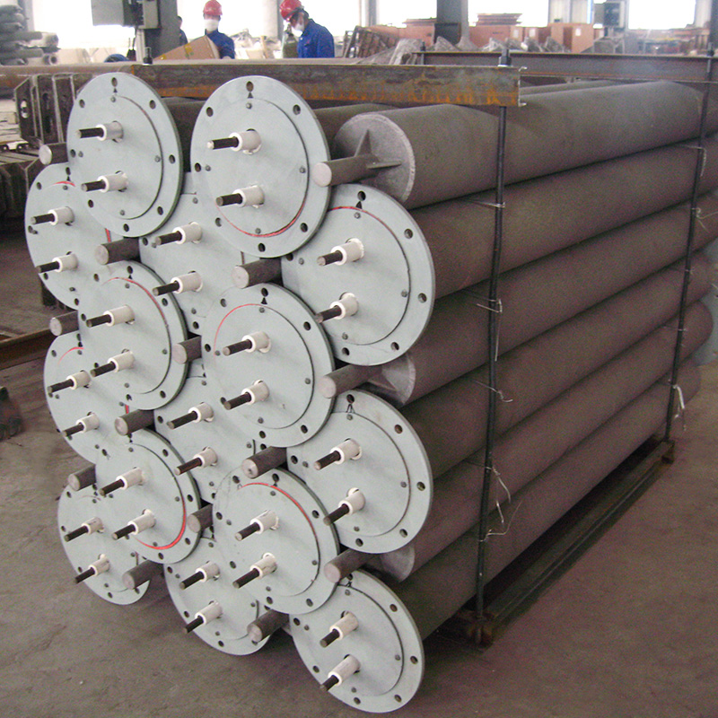
Rolled and welded tubes are fabricated by forming heat-resistant alloy sheet or plate into a cylindrical shape and welding the longitudinal seam. This manufacturing route allows the use of wrought alloy materials — which have better ductility and toughness than cast equivalents — and is more economical for medium-diameter tubes in moderate temperature service. The longitudinal weld is the potential weak point in a welded tube, and weld quality must be carefully controlled to ensure freedom from porosity, undercut, and residual stress concentrations that could initiate cracking under thermal cycling. For tempering furnace applications where temperatures are below 700°C and thermal cycling is moderate, welded tubes provide a cost-effective service life of three years or more.
Seamless tubes are produced by hot extrusion or rotary piercing of solid billets, producing a tube without any longitudinal weld seam. This eliminates the weld-related failure mode of welded tubes while providing the isotropic mechanical properties and consistent wall thickness of a wrought product. Seamless heat-resistant alloy tubes are available in a wide range of compositions including 310 stainless steel (25Cr-20Ni), 314 stainless (25Cr-20Ni-Si), and various high-alloy grades. They represent the best compromise between the high-temperature strength of centrifugally cast tubes and the ductility and toughness of wrought products, and are widely used in both quenching and tempering furnace radiant tube applications across the full operating temperature range of the product.
| Application | Furnace Temp. Range | Recommended Tube Type | Typical Tube Alloy | Expected Service Life |
|---|---|---|---|---|
| Tempering furnace | 150°C – 700°C | Welded or seamless | 304 / 316 stainless steel | ≥ 3 years |
| Annealing furnace | 600°C – 900°C | Seamless or centrifugal cast | 310S / 314 stainless steel | 2 – 3 years |
| Quenching / hardening furnace | 800°C – 1,050°C | Centrifugal cast | HK40 (25Cr-20Ni) or HP alloy | ≥ 1 year |
| Carburizing / nitriding furnace | 850°C – 1,050°C | Centrifugal cast | HK40 / HP with alumina former | 1 – 2 years |
| Gas-fired radiant tube | 900°C – 1,200°C | Centrifugal cast | HP / micro-alloy grades | ≥ 2 years |
Gas-fired radiant tubes operate on a fundamentally different energy input principle from electrically heated designs, though the external heat transfer mechanism — radiation from a hot tube surface — is identical. Understanding the gas-fired working principle is important because these tubes dominate in large-scale industrial heat treatment furnaces where gas energy costs are lower than electricity and where the very high power levels required (tens to hundreds of kilowatts per tube) make electric resistance heating impractical.
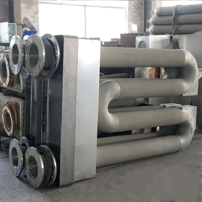
In a gas-fired radiant tube, a burner assembly at one end of the tube ignites a mixture of fuel gas (natural gas, LPG, or hydrogen) and combustion air. The burning gases travel along the inner bore of the tube at high velocity, transferring heat to the tube wall by forced convection. In straight-tube designs, the combustion gases exit at the opposite end through a flue connection. In recirculating designs — U-tube, W-tube, or P-tube configurations — the flue gases are redirected back along a return leg within the same tube assembly, recovering additional heat before exiting, improving thermal efficiency to values of 55 to 75% or higher with recuperative burner systems.
One of the principal design challenges in gas-fired radiant tubes is achieving uniform temperature distribution along the tube length. In a simple straight tube, the combustion gas temperature is highest near the burner and decreases along the tube as heat is transferred to the wall and the gas cools. This creates a temperature gradient along the tube that can cause non-uniform heating of the furnace load. The U-tube and W-tube configurations address this by folding the gas flow path so that the hottest combustion gas near the burner is positioned alongside the cooler return leg gas, allowing heat exchange between the forward and return passes that tends to equalize the outer surface temperature distribution. Advanced designs achieve outer wall temperature uniformity of ±20 to 40°C along the tube length, compared to gradients of 100°C or more in simple straight-tube designs.
Modern gas-fired radiant tubes often incorporate recuperative or regenerative heat recovery from the exhaust flue gas to preheat the incoming combustion air. In a recuperative system, a metallic heat exchanger built into the burner assembly transfers heat from the exiting flue gas to the incoming cold combustion air, raising the air temperature by 300°C to 500°C before combustion. This preheating reduces the fuel required to reach the target tube wall temperature, improving thermal efficiency by 20 to 35% compared to cold-air combustion. Regenerative systems use alternating ceramic heat storage beds to achieve even higher air preheat temperatures — approaching flue gas temperature minus a small approach temperature — delivering overall thermal efficiencies exceeding 80%.
The radiant tube's defining value in industrial heat treatment is not its thermal efficiency in isolation, but its ability to deliver high-temperature heat while maintaining a completely separate, chemically controlled atmosphere around the workpiece. This capability is the reason radiant tubes are used in virtually all atmosphere-controlled continuous and batch furnaces for heat treatment of metals.
Heat treatment processes such as bright annealing, carbonitriding, neutral hardening, and sintering require that the furnace atmosphere be precisely controlled to prevent oxidation, decarburization, or carburization of the workpiece surface. Any leakage of combustion gases (containing CO₂, H₂O, and O₂) or oxidizing air from an exposed heating element into the furnace atmosphere would immediately react with hot steel surfaces, producing scale, surface carbon changes, and dimensional variability that renders the treated parts defective.
The radiant tube isolates the heat source completely from the process atmosphere by sealing both the element and the combustion products (in gas-fired tubes) inside the protective outer tube. The outer tube is the only component in contact with both the furnace atmosphere on its outside and the heat source on its inside — and its gas-tight integrity is what makes controlled-atmosphere heat treatment possible at industrial scale.
Hydrogen atmosphere furnaces — used for bright annealing of stainless steel, sintering of powder metal parts, and copper brazing — require the strictest atmosphere control because hydrogen is both highly reducing (which prevents oxidation of the workpiece) and highly flammable. Direct electrical elements exposed to hydrogen atmosphere create explosion risk and potential element embrittlement. Radiant tubes in hydrogen furnaces maintain the element in air or in a separate inert gas, making them the only safe heating method for hydrogen atmosphere applications. The outer tube material must be carefully selected for hydrogen permeability resistance at elevated temperatures — this is one reason high-nickel alloys are preferred for hydrogen service, as they have lower hydrogen permeability than iron-based alloys.
The quantitative design of a radiant tube assembly involves balancing the power output requirements of the furnace against the thermal limits of both the heating element and the outer tube to achieve the required service life.
The surface load of the heating element — expressed in watts per square centimeter of element surface area — is the most critical parameter controlling element temperature and therefore service life. For nickel-chromium and iron-chromium alloy elements operating in radiant tube assemblies, the design surface load is typically constrained to ≤1 W/cm². This limit ensures that the element surface temperature does not rise excessively above the furnace temperature — typically remaining within 100 to 200°C above the tube wall temperature — keeping the element within its reliable oxidation-resistance range.
Exceeding the surface load limit causes accelerated oxidation of the element wire surface, which progressively thins the wire, increases its resistance, increases the power density further in a self-reinforcing cycle, and eventually leads to localized burnout. Designing within the surface load limit is therefore the primary means of ensuring the element service life that makes the product economically viable.
The single-tube power ratings of 3 kW to 60 kW cover the full range of heat treatment furnace requirements:
Furnace designers select the tube power rating and the number of tubes per zone to achieve the required installed power density — typically expressed in kW per square meter of hearth area — needed to reach set-point temperature in the specified heat-up time and maintain it under full production load.
Service life is the most commercially significant performance parameter of any radiant tube installation, as early failure requires costly unplanned maintenance shutdowns, replacement parts procurement, and potentially the scrapping of work-in-progress loads in the furnace. Understanding the factors that govern service life allows operators to maximize it through correct selection, installation, and operation.
Both the outer tube and the internal element degrade faster at higher operating temperatures due to accelerated oxidation, creep, and grain growth in the alloy microstructure. Each 50°C increase in tube wall temperature roughly doubles the oxidation rate of iron-chromium and nickel-chromium alloys. Thermal cycling — repeated heating and cooling — causes cyclic thermal stress in the tube wall and element because of differential thermal expansion between the tube, the element supports, and the ceramic insulators. This cycling fatigue is the primary failure mechanism in quenching furnaces, which experience frequent and rapid temperature swings during the quenching cycle. Minimizing unnecessary thermal cycling through proper furnace scheduling and slow, controlled heat-up rates significantly extends tube life in these applications.
The protective oxide layers that form on nickel-chromium and iron-chromium alloys — chromia (Cr₂O₃) and alumina (Al₂O₃) respectively — are what protect the alloy from further rapid oxidation at high temperatures. These layers can be disrupted by sulfur contamination, halide exposure, excessive moisture, or sudden changes in atmosphere chemistry (particularly switching between oxidizing and reducing conditions), leading to breakaway oxidation where the protective layer fails and rapid metal loss begins. Maintaining clean, consistent atmosphere chemistry inside the furnace — and ensuring the element compartment of the radiant tube is free from contamination — is essential for achieving the rated service lives of ≥1 year in quenching furnaces, ≥3 years in tempering furnaces, and ≥2 years for gas-fired tubes.
Long radiant tubes spanning wide furnace chambers without intermediate support can sag under their own weight at elevated temperatures due to high-temperature creep in the tube alloy. This sagging causes bending stress in the tube wall that can lead to cracking — particularly at the point where the tube exits the furnace wall, where steep temperature gradients create high thermal stress. Proper tube support design — using correct spacing of support brackets, ensuring tubes are not over-span, and selecting alloys with adequate creep resistance for the operating temperature — is essential for achieving full service life without mechanical failure.
Radiant tubes are used across virtually the full spectrum of controlled-atmosphere heat treatment processes in the metalworking industry. The following table summarizes the principal applications, their furnace temperature ranges, and the specific role radiant tubes play in each process:
| Heat Treatment Process | Temperature Range | Furnace Atmosphere | Role of Radiant Tube |
|---|---|---|---|
| Tempering | 150°C – 700°C | Air or nitrogen | Uniform heating without hot spots; controlled temperature precision |
| Bright annealing | 700°C – 1,100°C | Hydrogen or dissociated ammonia | Isolates combustion from H₂ atmosphere; enables bright surface finish |
| Neutral hardening / quenching | 800°C – 1,050°C | Endothermic / nitrogen-methanol | Prevents decarburization; maintains carbon potential in atmosphere |
| Carburizing | 880°C – 1,000°C | Enriched endothermic gas | Heats without disturbing controlled carbon potential atmosphere |
| Nitriding | 480°C – 570°C | Ammonia or ammonia/nitrogen | Maintains nitriding potential without atmosphere contamination |
| Copper brazing / sintering | 900°C – 1,150°C | Hydrogen or hydrogen/nitrogen | Safe heating in explosive H₂ atmosphere; prevents oxidation |
Radiant tubes designed for modern heat treatment applications must be compatible with a wide range of furnace platforms — both domestic equipment manufactured to national standards and imported systems engineered to European, American, or Japanese specifications. This compatibility requirement drives the importance of dimensional standardization, coupling interface options, and the ability to customize tube length, diameter, power rating, and element configuration to match the original equipment manufacturer's specifications.
Key dimensional parameters that must be matched for replacement tube compatibility include:
The ability to produce radiant tubes as direct replacement components for imported heat treatment systems — manufactured to the same dimensional and electrical specifications as the original equipment — eliminates the need for costly imported replacement parts and significantly reduces the lead time and cost of furnace maintenance. This compatibility with both domestic and imported equipment platforms is one of the most practically valuable characteristics of a well-engineered radiant tube product line.
We will reply to you as soon as possible.
 custom alloys for sale
wholesale different alloys
custom alloys for sale
wholesale different alloys