No. 308, Gongxin Road, Industrial Park, Dongxing Town, Jingjiang City, Jiangsu Province, China
 [email protected]/ [email protected]
 English
 Español
 русский
 中文简体
中文简体 No. 308, Gongxin Road, Industrial Park, Dongxing Town, Jingjiang City, Jiangsu Province, China[email protected]/ [email protected]
The service life of a Radiant Tube typically ranges from 3 to 10 years under continuous industrial furnace operation, with the actual figure depending heavily on the alloy grade used, the operating temperature, the furnace atmosphere, the thermal cycling frequency, and the quality of installation and maintenance practices. Radiant tubes manufactured from premium centrifugally cast high-temperature alloys such as HP40Nb operating within their rated temperature envelope and subjected to controlled, gradual thermal cycling commonly achieve service life at the upper end of this range, while tubes operated above their design temperature, subjected to frequent rapid thermal shock, or manufactured from lower-grade alloys frequently fail well within 3 years.
Radiant tube life is not a fixed number -- it is the outcome of an interaction between metallurgical design, operating conditions, and maintenance discipline. Understanding the specific failure mechanisms that limit radiant tube life, and the design and operational levers available to extend it, allows furnace operators to make informed decisions about alloy selection, operating practice, and maintenance scheduling that directly affect furnace uptime and replacement cost.
Content
A radiant tube is a sealed metal tube installed within an industrial furnace that contains a gas or oil burner flame and combustion products on its interior, transmitting heat to the furnace chamber and the process load by radiation from its hot outer surface, without the combustion gases ever contacting the product being processed. This indirect heating principle is essential in applications such as heat treatment furnaces, continuous annealing lines, galvanizing furnaces, and other processes where the atmosphere inside the furnace chamber must be controlled or kept free of combustion byproducts.
Because radiant tubes operate at the interface between an open flame internally and a high-temperature furnace atmosphere externally -- often simultaneously exposed to oxidizing conditions on the outside and reducing or carburizing conditions on the inside -- they are among the most thermally and chemically stressed components in any furnace system. Radiant tube replacement is one of the largest recurring maintenance costs in continuous furnace operations, and unplanned tube failure causes furnace downtime, potential damage to the process load, and in some cases safety incidents from combustion gas leakage. Understanding and extending radiant tube service life therefore has a direct and measurable impact on furnace operating economics.
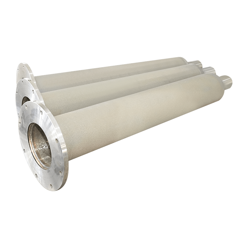
Radiant tube service life is governed by a combination of material, design, and operational factors. The following factors are the most significant determinants of how long a given radiant tube will remain in safe and effective service.
Every radiant tube alloy has a maximum continuous operating temperature above which creep deformation and oxidation rates accelerate sharply. Operating a radiant tube even 50 degrees C above its rated maximum continuous temperature can reduce service life by 50 percent or more, according to data published by the American Society for Metals (ASM International, asminternational.org) on creep-rupture behavior of heat-resistant cast alloys. This sensitivity arises because creep rate follows an exponential (Arrhenius-type) relationship with temperature, meaning that relatively small temperature increases produce disproportionately large reductions in rupture life.
Radiant tubes that are repeatedly heated and cooled -- whether from furnace startup and shutdown cycles, process interruptions, or batch-type operation -- experience thermal fatigue damage in addition to the steady-state creep and oxidation that occurs during continuous operation. Each thermal cycle induces differential expansion stresses between the tube's hot and cold zones and between the inner and outer tube surfaces. Frequent rapid thermal cycling is one of the most common causes of premature radiant tube failure, often producing circumferential cracking at the weld seams or at points of structural restraint well before the tube reaches its creep-limited service life under steady-state conditions.
The chemical composition of both the internal combustion atmosphere and the external furnace atmosphere significantly affects radiant tube degradation rates. Carburizing atmospheres, sulfur-containing fuel impurities, and high-moisture combustion conditions all accelerate internal surface degradation, while externally, atmospheres containing chlorine, sulfur compounds, or fluctuating oxygen partial pressure accelerate external scale formation and spallation. Tubes operating in carburizing furnace atmospheres for case-hardening processes typically experience faster internal surface attack than equivalent tubes in neutral or oxidizing atmosphere furnaces.
Tube wall thickness directly determines the cross-sectional area available to carry the stresses induced by internal pressure, self-weight, and thermal gradients. Thinner-wall tubes reach a given fraction of remaining wall thickness sooner as oxidation progressively consumes metal from both internal and external surfaces. Tube geometry -- straight, U-type, W-type, or single-ended recuperative -- also affects service life, as more complex geometries with multiple bends or weld joints introduce additional stress concentration points where failures are statistically more likely to initiate.
The alloy from which a radiant tube is manufactured is the single most influential design decision affecting service life, because it determines the tube's creep strength, oxidation resistance, and carburization resistance at the intended operating temperature. The table below summarizes typical service life ranges for the alloy families most commonly used in radiant tube manufacturing.
| Alloy Type | Typical Composition | Max Continuous Temperature | Typical Service Life |
|---|---|---|---|
| HH (25Cr-12Ni) | Heat-resistant cast stainless | 900 to 950 degrees C | 1 to 3 years |
| HK40 (25Cr-20Ni) | Heat-resistant cast stainless | 1000 to 1050 degrees C | 3 to 5 years |
| HP40 (25Cr-35Ni) | High-nickel heat-resistant cast alloy | 1050 to 1100 degrees C | 4 to 7 years |
| HP40Nb (25Cr-35Ni-Nb) | Niobium-stabilized high-nickel alloy | 1100 to 1150 degrees C | 5 to 10 years |
| Alloy 600 / 601 | Wrought nickel-chromium alloy | 1100 to 1150 degrees C | 6 to 10 years |
The progression from HH through HK40, HP40, and HP40Nb reflects increasing nickel content and the addition of niobium carbide-forming stabilizers, both of which improve high-temperature creep strength and carbide stability. The niobium-stabilized HP40Nb alloy is widely regarded as the standard for demanding continuous furnace applications because the niobium carbides that form during service are more stable at high temperature than the chromium carbides present in unstabilized grades, reducing the rate of intergranular carbide coarsening that otherwise degrades creep strength over extended service.
Radiant tubes do not fail randomly -- they fail through a small number of well-understood degradation mechanisms, each of which leaves characteristic evidence that experienced furnace maintenance personnel use to diagnose the root cause and adjust operating practice accordingly.
Creep is the slow, time-dependent plastic deformation of metal under sustained stress at elevated temperature. In radiant tubes, creep manifests as gradual sagging of horizontal tube sections under their own self-weight, particularly between support points. Excessive sag reduces clearance to adjacent furnace structures, can cause the tube to contact refractory or other tubes, and in advanced stages leads to localized thinning and eventual rupture at the point of maximum deformation. Properly spaced tube supports and hangers, combined with operation within the alloy's rated temperature, are the primary mitigations against creep-driven failure.
At elevated temperature, the external surface of the radiant tube reacts with oxygen in the furnace atmosphere to form a protective chromium oxide scale. Under steady-state conditions this scale is protective and slows further oxidation, but repeated thermal cycling causes the scale to crack and spall (flake off) due to the mismatch in thermal expansion between the oxide scale and the underlying metal. Each spallation event exposes fresh metal surface to renewed oxidation, and the cumulative effect of repeated cycling can be a significantly higher metal loss rate than steady-state oxidation alone would predict.
In furnaces with carbon-rich internal combustion atmospheres or external carburizing process atmospheres, carbon can diffuse into the tube wall, forming chromium carbides that increase hardness but reduce ductility and toughness in the affected zone. Carburized radiant tube material becomes increasingly brittle over time and susceptible to cracking under thermal cycling stresses that the original, more ductile microstructure would have accommodated without damage. Carburization is typically irreversible once it has progressed significantly into the tube wall.
Thermal fatigue cracks typically initiate at locations of structural restraint or stress concentration -- weld seams, support points, flange connections, or transitions between straight and curved tube sections -- and propagate with each subsequent thermal cycle. Thermal fatigue is frequently the dominant failure mode in furnaces with frequent startup-shutdown cycles or batch processing operations, as opposed to furnaces running continuously for extended periods, where creep and oxidation tend to dominate the failure mechanism instead.
Beyond alloy selection, the manufacturing process used to produce a radiant tube significantly affects its achievable service life, because manufacturing quality determines the consistency of the microstructure, the presence or absence of internal casting defects, and the dimensional accuracy of the finished tube.
Centrifugally cast radiant tubes are produced by pouring molten alloy into a rotating mold, where centrifugal force compacts the metal against the mold wall as it solidifies. This process produces a denser, more uniform microstructure with fewer internal porosity defects compared to static (gravity) casting methods, directly translating into improved creep strength and more consistent service life across the tube population. Centrifugal casting is the standard production method for premium radiant tubes intended for demanding, long-service-life applications, as the improved metallurgical soundness reduces the incidence of early, defect-initiated failures that can otherwise occur well before the statistically expected creep-limited life.
Uniform wall thickness around the tube circumference and along its length ensures that stress is distributed evenly under both internal pressure and thermal gradient loading. Localized thin spots -- whether from casting defects or subsequent machining errors -- become preferential sites for accelerated oxidation penetration and creep rupture, effectively reducing the tube's service life to that of its weakest cross-section rather than its nominal average wall thickness.
Post-casting heat treatment, where specified by the alloy and application, relieves residual casting stresses and can optimize the as-cast microstructure for improved high-temperature performance. Tubes that have not received appropriate post-casting heat treatment may exhibit reduced ductility or accelerated stress-relaxation cracking when first placed into service, an early-life failure mode distinct from the longer-term creep and oxidation mechanisms that govern the bulk of the tube's expected service life.
Furnace operators have direct control over several operational variables that significantly influence how close to its maximum theoretical life a radiant tube will actually achieve in service.
Recognizing the warning signs of approaching radiant tube failure allows maintenance teams to schedule replacement during planned downtime rather than experiencing an unplanned outage. The following indicators are commonly used by furnace maintenance teams to assess remaining radiant tube life.
Radiant tube configuration -- straight single-ended, U-type, W-type, or P-type recuperative -- affects not only thermal efficiency and furnace layout but also the typical failure locations and relative service life achieved in practice, due to differences in the number and location of weld joints and bends.
| Tube Configuration | Relative Weld Joint Count | Common Failure Location | Relative Service Life Profile |
|---|---|---|---|
| Straight single-ended | Low | Mid-span sag, hot-end oxidation | Generally longest, fewest stress points |
| U-type | Medium | Bend section, weld seam | Moderate, bend region is critical zone |
| W-type | High | Multiple bend sections and welds | Shorter on average due to multiple stress points |
| Recuperative (P-type) | Medium to High | Inner recuperator tube, end seal welds | Variable, depends on recuperator tube condition |
The economic impact of radiant tube service life extends well beyond the direct cost of the replacement tube itself. Furnace downtime for tube replacement, lost production during the changeover, and in continuous processing lines, the cost of restarting and re-stabilizing the process after a shutdown, frequently represent a larger total cost than the tube hardware itself.
Consider a continuous annealing furnace with radiant tubes averaging 4 years of service life versus an alternative specification achieving 8 years of service life under the same operating conditions. Doubling the service life halves the frequency of replacement events, directly halving the cumulative downtime, labor cost, and production disruption associated with tube replacement over any given multi-year operating horizon -- even before accounting for any difference in the upfront cost of the longer-life tube specification. This is the underlying economic rationale for specifying premium alloy grades such as HP40Nb, or centrifugally cast tubes with superior metallurgical consistency, in continuous, high-utilization furnace applications where downtime cost is significant.
Selecting a radiant tube specification that achieves the longest practical service life for a given application requires matching alloy grade, wall thickness, and tube geometry to the specific operating temperature, atmosphere, and cycling profile of the furnace in question, rather than defaulting to a generic specification across all furnace zones and applications.
For furnace operators seeking to extend service intervals and reduce the total lifecycle cost of furnace radiant heating systems, the Radiant Tube product range engineered for high-temperature industrial furnace applications offers alloy grades and casting quality specifically suited to achieving the upper end of the service life ranges discussed throughout this article, supporting more predictable maintenance planning and reduced unplanned downtime across continuous and batch furnace operations alike.
We will reply to you as soon as possible.
 custom alloys for sale
wholesale different alloys
custom alloys for sale
wholesale different alloys