No. 308, Gongxin Road, Industrial Park, Dongxing Town, Jingjiang City, Jiangsu Province, China
 [email protected]/ [email protected]
 English
 Español
 русский
 中文简体
中文简体 No. 308, Gongxin Road, Industrial Park, Dongxing Town, Jingjiang City, Jiangsu Province, China[email protected]/ [email protected]
A radiant tube is a sealed, indirect heating element used in industrial furnaces and heat treatment equipment to transfer heat to the workpiece or furnace atmosphere without any direct contact between the combustion gases or electrical heating element and the material being processed. The tube encases the heat source — either a gas burner or an electric resistance element — within a protective outer shell, and transmits the generated heat outward by thermal radiation and convection. This isolation makes radiant tubes the essential heating solution wherever the furnace atmosphere must be precisely controlled, such as in protective gas, vacuum-adjacent, or atmosphere-sensitive heat treatment processes.
Radiant tubes are found in a wide range of industrial heat treatment applications including carburizing furnaces, nitriding furnaces, bright annealing lines, continuous sintering furnaces, quenching and tempering systems, and galvanizing lines. They are available in both gas-fired and electrically heated configurations, with outer tube materials ranging from high-alloy centrifugally cast steel to ceramic, and with single-tube power ratings from 3 kW up to 60 kW for electrical types, or multi-megawatt installations for large gas-fired furnace systems.
Content
The operating principle of a radiant tube is straightforward in concept but demanding in engineering execution. The heat source — whether a gas flame or an electrical resistance element — is contained entirely within the inner channel of the tube. Heat generated inside the tube conducts through the tube wall and is then radiated outward from the outer surface into the furnace chamber, where it heats the workpieces and the surrounding atmosphere.
This arrangement creates a complete physical and chemical barrier between the heating medium (combustion products or electrical element) and the furnace atmosphere (typically nitrogen, hydrogen, ammonia dissociate, or other protective gases). The significance of this separation cannot be overstated in heat treatment applications:
Heat transfer from the outer tube surface to the furnace interior occurs through a combination of radiation (dominant at temperatures above approximately 600°C, following the Stefan-Boltzmann law with heat flux proportional to the fourth power of absolute temperature) and convection from circulation of the furnace atmosphere. At typical operating temperatures of 900°C to 1,100°C, radiation accounts for 70 to 90% of total heat transfer, explaining both the name "radiant tube" and the critical importance of tube emissivity, surface temperature, and geometric view factor in furnace thermal design.
Radiant tubes are manufactured and operated in two fundamentally different configurations — gas-fired and electrically heated — each with distinct advantages, design requirements, and application profiles. Understanding the differences is essential when selecting a radiant tube for a specific furnace application.
Gas-fired radiant tubes use a burner assembly mounted at one or both ends of the tube to combust natural gas, liquefied petroleum gas, or other fuel gases within the enclosed tube interior. The combustion products travel through the tube length, transferring heat through the tube wall by conduction, and are exhausted from the opposite end of the tube — either directly to atmosphere or through a heat recovery recuperator that preheats the incoming combustion air.
Gas-fired radiant tubes are the dominant choice for large industrial continuous furnaces — strip annealing lines, galvanizing lines, and continuous carburizing furnaces — where the total heat input requirement is in the range of hundreds of kilowatts to several megawatts. Natural gas is typically less expensive per unit of heat than electricity in most industrial markets, making gas-fired radiant tubes more economical for high-throughput, continuous-operation furnaces.
The service life target for quality gas-fired radiant tubes is at least 2 years of continuous or cyclic operation, depending on operating temperature and thermal cycling frequency. High-alloy outer tubes — typically containing 25% chromium, 20% nickel, and additions of silicon, niobium, or rare earth elements — are required to withstand the combination of high temperature, oxidizing interior combustion atmosphere, and potentially carburizing or nitriding exterior furnace atmosphere simultaneously.
Electrically heated radiant tubes house a resistance heating element — the tube core — inside the outer protective tube. Electrical current passes through the resistance element, generating heat that conducts and radiates outward through the tube wall. The outer tube serves simultaneously as mechanical support for the heating element and as a sealed protective barrier between the element and the furnace atmosphere.
Electric radiant tubes offer significant operational advantages in specific applications:
Single-tube power ratings for electric radiant tubes typically range from 3 kW for small laboratory or light-duty furnaces up to 60 kW for large industrial heat treatment chambers. Multiple tubes are installed in parallel to achieve the total furnace power requirement — a 200 kW furnace might use ten 20 kW radiant tubes, for example, arranged to achieve uniform temperature distribution.
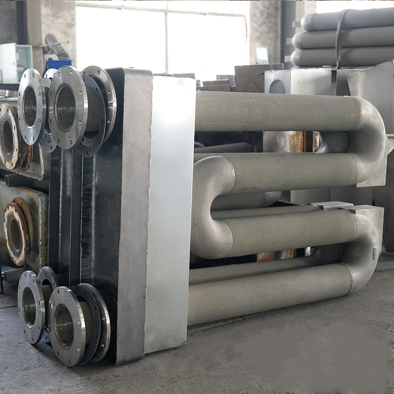
In electrically heated radiant tubes, the inner heating element — the tube core — is the component that generates the heat. Its design governs the surface load distribution, the temperature uniformity along the tube length, the electrical characteristics of the tube, and ultimately the service life of the entire assembly. Three principal core configurations are used in industrial radiant tubes.
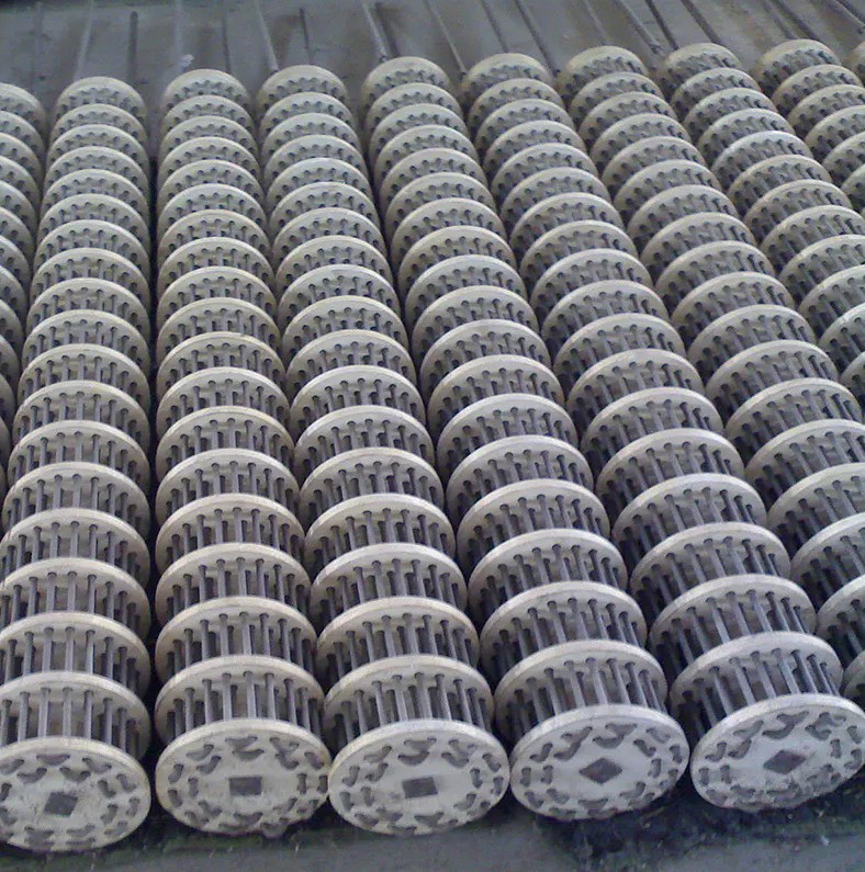
The cage-type element consists of straight or slightly corrugated resistance wire or strip segments held in a cylindrical framework — conceptually similar to a squirrel cage motor rotor geometry. The cage configuration provides good mechanical rigidity, allows thermal expansion along the element length without stress concentration, and facilitates even current distribution across parallel element segments. Cage elements are well-suited to medium and high power radiant tubes where mechanical robustness and reliable current sharing between parallel paths are priorities.
The vertical strip-wound element uses flat resistance strip wound in a helical or serpentine pattern around a central support structure, with the strip oriented with its flat face generally parallel to the tube axis. This geometry increases the effective radiation surface area relative to a round wire element of equivalent cross-section, improving heat transfer efficiency from element to tube inner wall. Strip-wound elements are commonly used in medium-power applications where uniform temperature distribution along the tube length is a design priority.
The spiral-wound element — essentially a helical coil of resistance wire — is the most straightforward geometry and the most widely used configuration in standard radiant tube cores. The helix pitch determines the resistance per unit length and the surface load distribution. Closely wound spirals produce higher surface loads per unit area; open-pitch spirals allow better air circulation around the wire and reduce hot-spot risk. The spiral coil configuration accommodates thermal expansion well — the coil simply shortens or lengthens axially — making it mechanically tolerant of the large thermal excursions experienced in intermittent-operation furnaces.
The resistance wire or strip forming the heating element is manufactured from either nickel-chromium (Ni-Cr) or iron-chromium-aluminum (Fe-Cr-Al) alloys, each offering different performance characteristics matched to different operating temperature ranges and environments.
| Property | Nickel-Chromium (Ni-Cr) Alloys | Iron-Chromium (Fe-Cr-Al) Alloys |
|---|---|---|
| Maximum service temperature | Up to approximately 1,150°C | Up to approximately 1,300°C |
| Oxidation resistance | Good — Cr₂O₃ scale | Excellent — Al₂O₃ scale (more protective) |
| Ductility at room temperature | Good — easily formed and welded | Lower — becomes brittle after high-temp service |
| Resistance stability over life | Good — stable resistivity | Resistance increases slowly with oxidation |
| Carburizing atmosphere resistance | Moderate — can be carburized | Better — alumina scale provides barrier |
| Typical applications | 500°C – 1,100°C; tempering, annealing | 900°C – 1,300°C; high-temp processes |
The surface load of the heating element — defined as the electrical power dissipated per unit surface area of the resistance wire — is a critical design parameter that governs element temperature and service life. A surface load design value of ≤1 W/cm² is the standard specification for quality radiant tube elements, ensuring that the element wire temperature remains within safe limits relative to its melting point and oxidation threshold. Operating the element at higher surface loads accelerates oxidation and reduces service life disproportionately — even a modest increase above the design surface load can halve element life through accelerated oxide scale growth and depletion of the protective-scale-forming elements (chromium or aluminum) in the alloy.
The operating temperature range of the heating element spans from 500°C to 1,300°C depending on the alloy grade and specific application, covering the full range of industrial heat treatment processes from low-temperature tempering and aging treatments through high-temperature sintering and brazing operations.
The outer protective tube is the component exposed to the furnace atmosphere and workpiece radiation, and it must withstand the full severity of the furnace environment — high temperature, thermal cycling, potentially carburizing, nitriding, or sulfurizing atmospheres, and mechanical loads from its own weight and mounting constraints. Three manufacturing methods are used to produce outer radiant tubes, each with distinct characteristics.
Centrifugal casting is the highest-performance manufacturing method for large-diameter, heavy-wall radiant tubes. In this process, molten high-alloy steel is poured into a rapidly rotating cylindrical mold, and centrifugal force distributes the liquid metal uniformly against the mold wall as it solidifies. This produces a tube with a dense, refined grain structure, high alloy homogeneity, and excellent dimensional consistency.
Centrifugally cast tubes are manufactured from heat-resistant alloys with high chromium and nickel content — typical compositions include 25Cr-20Ni, 25Cr-35Ni, HK40, HP40, and micro-alloyed variants with additions of niobium, tungsten, or rare earth elements that further improve creep strength and oxidation resistance at extreme temperatures. These alloys are chosen specifically for their combination of:
Centrifugally cast tubes are the preferred choice for the most demanding applications — high-power quenching furnaces, high-temperature carburizing systems, and continuous industrial lines where tube failure requires production shutdown with severe economic consequences.
Rolled and welded tubes are fabricated by rolling flat heat-resistant alloy plate or sheet into a cylindrical form and welding the longitudinal seam using appropriate filler materials and welding procedures. This manufacturing method enables the production of tubes in a wider range of alloy grades — including grades available as wrought plate but not as standard centrifugal casting alloys — and allows larger diameters and thinner wall thicknesses than centrifugal casting economically permits.
The longitudinal weld seam is the critical area in rolled and welded tubes — the weld must be of full penetration quality with properties matching the parent material, and must be inspected by radiography or ultrasonic testing to ensure freedom from porosity, incomplete fusion, and other weld defects that could fail under thermal cycling stresses. Quality rolled and welded tubes with properly executed and inspected welds perform comparably to centrifugally cast tubes in many standard heat treatment applications.
Seamless radiant tubes are manufactured by hot extrusion, hot piercing, or rotary piercing of solid bar stock — processes that produce a tube with no longitudinal weld seam and a wrought, worked microstructure throughout the wall thickness. Seamless tubes in standard austenitic and heat-resistant alloy grades offer excellent mechanical properties and freedom from weld-related defects, making them a reliable choice for medium-duty radiant tube applications.
The practical limitation of seamless tubes for radiant tube applications is the available size range — seamless tube production in high-alloy materials is practical up to approximately 200mm outer diameter and wall thicknesses compatible with extruder or piercing mill capabilities. For larger diameters or very thick walls required by high-power applications, centrifugal casting or rolled and welded construction becomes necessary.
Radiant tubes are manufactured and installed in several geometric configurations that match different furnace designs, heating zone layouts, and space constraints. The tube shape affects the heat distribution pattern within the furnace, the pressure drop of combustion gases (for gas-fired types), and the mechanical support requirements.
The straight or I-type radiant tube is the simplest geometry — a single straight tube heated from one end (for gas types) or along its full length (for electric types). Straight tubes are mounted horizontally through opposing furnace walls or vertically through the furnace top or bottom, with the tube axis perpendicular to or along the furnace chamber. They are used in box furnaces, pit furnaces, retort furnaces, and continuous pusher furnaces where their simple mounting and replacement geometry minimizes downtime during maintenance.
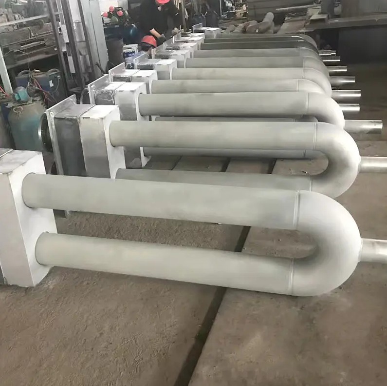
U-type radiant tubes consist of two parallel straight legs connected by a 180° bend at the far end from the burner. The burner is mounted at the open end of one leg, combustion gases travel down that leg, around the bend, and back up the return leg to the exhaust port — which is adjacent to the burner on the same furnace wall face. This configuration allows both the combustion air/gas inlet and the flue gas exhaust to be located on a single furnace wall, simplifying external piping and enabling more flexible furnace chamber layout. U-type tubes are among the most widely used configurations in industrial controlled-atmosphere furnaces.
P-type tubes add a second 180° bend to create a configuration with three parallel passes, while W-type tubes extend this to four passes. These multi-pass configurations maximize the total tube length within a given furnace wall spacing, increasing the heat transfer surface area per mounting penetration through the furnace wall. They are used in continuous furnaces with limited wall-to-wall depth where maximizing heating capacity per mounting position is a priority. The additional bends in P and W configurations introduce greater thermal stress concentration and require more careful material and manufacturing specification to achieve adequate service life.
Advanced gas-fired radiant tube systems use regenerative or recirculating burner configurations where the combustion air is preheated by recovering heat from the outgoing flue gases through a ceramic or metallic regenerator or recuperator integrated into the burner assembly. Regenerative burner radiant tubes can achieve combustion air preheat temperatures of 800°C to 1,000°C, dramatically improving thermal efficiency compared to cold-air combustion. Fuel savings of 30–50% compared to cold-air burner systems are achievable with regenerative firing, making these systems economically attractive for continuous high-temperature furnaces despite their higher initial cost.
Radiant tubes are used across a wide spectrum of industrial heat treatment operations, wherever controlled atmosphere integrity must be maintained simultaneously with high-temperature heating. The following table summarizes the principal application areas with their characteristic operating conditions and tube requirements.
| Application | Temperature Range | Furnace Atmosphere | Tube Type Preferred | Min. Service Life |
|---|---|---|---|---|
| Gas / Atmosphere Carburizing | 880°C – 980°C | Endothermic gas (CO/H₂) | Centrifugally cast, gas-fired | ≥1 year (quench cycle) |
| Quenching Furnaces | 830°C – 950°C | Protective N₂ / endothermic | Gas or electric, high-alloy tube | ≥1 year |
| Tempering Furnaces | 150°C – 700°C | Air or protective gas | Electric, standard alloy tube | ≥3 years |
| Bright Annealing | 800°C – 1,120°C | Hydrogen or H₂/N₂ | Gas or electric, H₂-compatible | ≥2 years |
| Nitriding Furnaces | 480°C – 580°C | Ammonia / N₂ mixture | Electric, Ni-bearing alloy tube | ≥3 years |
| Continuous Strip Annealing | 700°C – 1,000°C | HNx (H₂ + N₂ mixture) | Gas-fired, cast or seamless | ≥2 years continuous |
| Sintering Furnaces | 900°C – 1,300°C | Hydrogen or dissociated NH₃ | Electric, Fe-Cr-Al element, refractory tube | ≥2 years |
Radiant tube service life varies considerably depending on the application, operating temperature, thermal cycling frequency, atmosphere aggressiveness, and tube material quality. Understanding the expected service life for different applications helps maintenance planners schedule preventive replacement and avoid unplanned production shutdowns.
Typical minimum service life targets for quality radiant tubes are:
Understanding the mechanisms by which radiant tubes fail helps operators make better maintenance decisions and select appropriate tube specifications for their specific operating conditions.
The case for using radiant tubes rather than direct-fired burners or open resistance elements — where the heating source is directly exposed to the furnace atmosphere and workpiece — rests on a combination of process quality, safety, flexibility, and operational advantages that in atmosphere-critical applications are not optional considerations but fundamental requirements.
Selecting the correct radiant tube for a given application requires evaluating several interdependent parameters. The following checklist provides a systematic framework for making this selection correctly.
Radiant tubes specified and manufactured correctly for their intended application will deliver the minimum service life targets — at least one year in quenching service, three years in tempering service, and two years for gas-fired types — providing reliable, consistent heating performance that protects both production throughput and the metallurgical quality of every heat-treated component that passes through the furnace.
We will reply to you as soon as possible.
 custom alloys for sale
wholesale different alloys
custom alloys for sale
wholesale different alloys